Get in touch with Shengtu Bufan Company

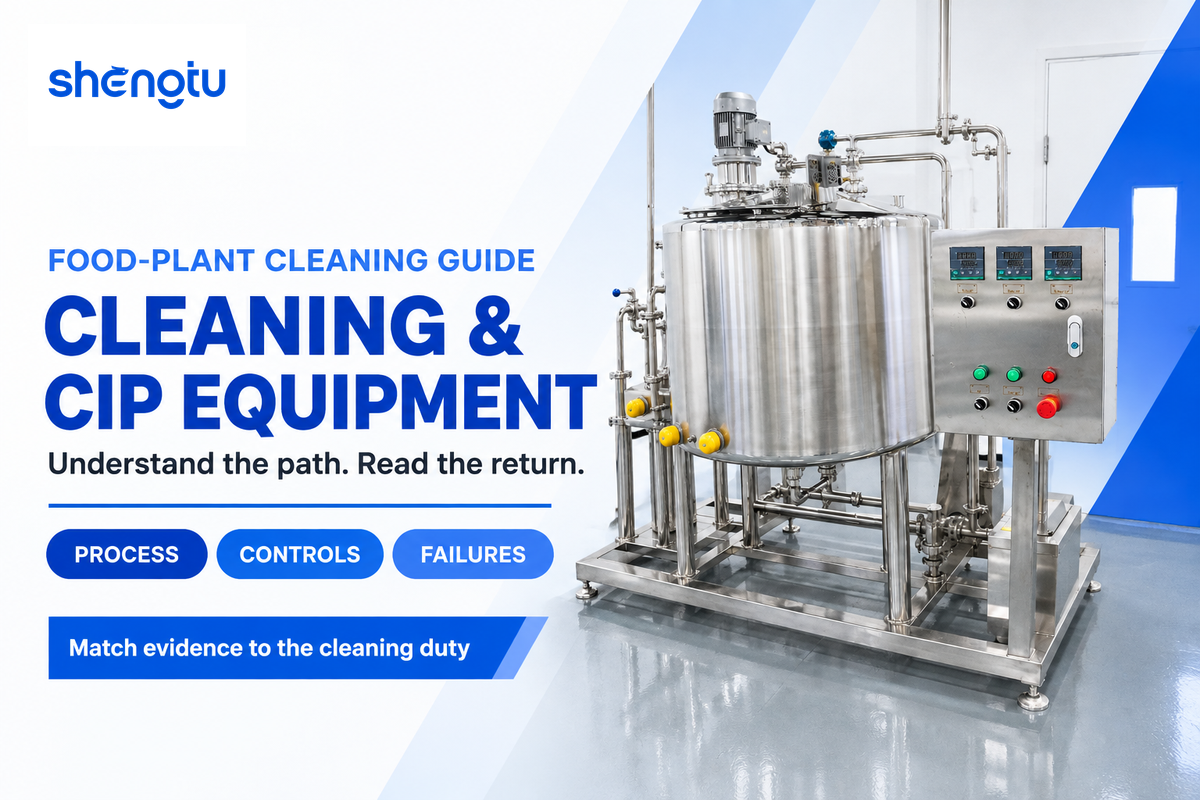
Cleaning & CIP Equipment removes food deposits from processing surfaces using a combination of mechanical action, temperature, time and appropriate chemistry. A clean-in-place system circulates cleaning fluids through a closed system. Automated cleaning supports a food safety program when its method and checks suit the application. Its usefulness starts with a practical question: which surfaces actually receive the required cleaning action?
By Cherry, SHENGTU · Updated October 2026
Quick guide: food-plant CIP
- Purpose: internal cleaning of equipment designed for circulation, flooding or spray cleaning.
- Operating evidence: circuit identity, effective contact time, temperature, chemistry and hydraulic delivery.
- Separate questions: soil removal, sanitization, allergen removal and production release.
- Cost denominator: accepted cleaning events, including repeat attempts.
Cleaning & CIP Equipment cleans defined process surfaces with controlled cleaning fluids. Effective CIP requires contact, suitable chemistry and mechanical action at the equipment, followed by checks matched to the residue and next product.
Key points
- A completed skid sequence can coexist with an unclean branch or shadowed tank surface.
- CIP, clean-out-of-place and manual cleaning can all belong on the same production line.
- Pipe flow and tank spray coverage require different hydraulic checks.
- A cheaper cleaning attempt can cost more per accepted changeover when repeat cleaning rises.
For food and beverage production, the difficult decisions usually sit between departments. The Engineering department pushes for a circuit to deliver the process recipe. The Quality department wants release verification. Production needs a changeover window, while Finance wants to know the cost. Treating the situation as one pump-selection challenge causes gaps.
What Cleaning and CIP Equipment Actually Cleans
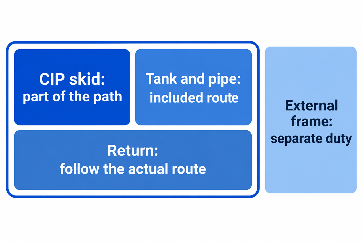
Cleaning Equipment is used to remove soil from surfaces assigned to it by its method of cleaning. CIP Equipment is used to serve a path that’s product-contact and is able to receive an effective cleaning solution and mechanical action. Product washers, external foam cleaning, removable part washers and sanitation of floors perform different functions, even if the same food factory needs all of them.
What is CIP equipment?
CIP equipment is a combination of tanks, pumps, heaters, dosers, valves, instruments and controls used for cleaning connected process equipment without routine dismantling of the closed system. The complete cleaning path includes the process equipment and piping. A skid by itself is only a part of that path.
A tank spray device is an example. The skid can deliver hot detergent, but the tank also needs an adequate spray pattern and sufficient drainage to maintain cleaning action. A pipe circuit requires an intended flow path through its branches. An external surface receives no treatment whatsoever simply because the skid is running.
Oklahoma State University’s CIP fact sheet defines contact via spray heads or flooding, and identifies equipment selection, cleaning variables and testing as related tasks. Calling every stainless steel piece of equipment “CIP ready” isn’t particularly helpful. Whether or not cleaning action can work depends on the accessibility of the surface and the installed route.
Keep the three endpoints of cleaning, sanitization and sterilization distinct. An automated CIP system can repeat programmed actions, but it does not turn those endpoints into synonyms. A clean-looking line and an accepted allergen changeover also require different questions.
Consider a sauce line with a jacketed mixing vessel, transfer pipe and filler. The vessel and pipe may have an included CIP route; filler nozzles may require a separate procedure; manually cleaning external frames remains a separate duty. A hose may be part of the circuit if its design and connections support that. Another hose with an unsuitable route or inaccessible residue pocket may need removal. The component name alone doesn’t decide the method.
Draw boundaries around surface areas rather than around purchased machines. Show where the cleaning fluid enters, what valves change position, where it returns and what surfaces remain outside the path. This drawing establishes a mutually understood basis for the discussion on cycle times, chemical consumption, and quality.
Once this boundary is set, the next step is to consult SHENGTU’s Cleaning & CIP Equipment Solutions page to correlate cleaning tasks to project design. The operating instructions and equipment scope must be aligned as to what’s included.
How a CIP Cleaning Process Moves Soil Out
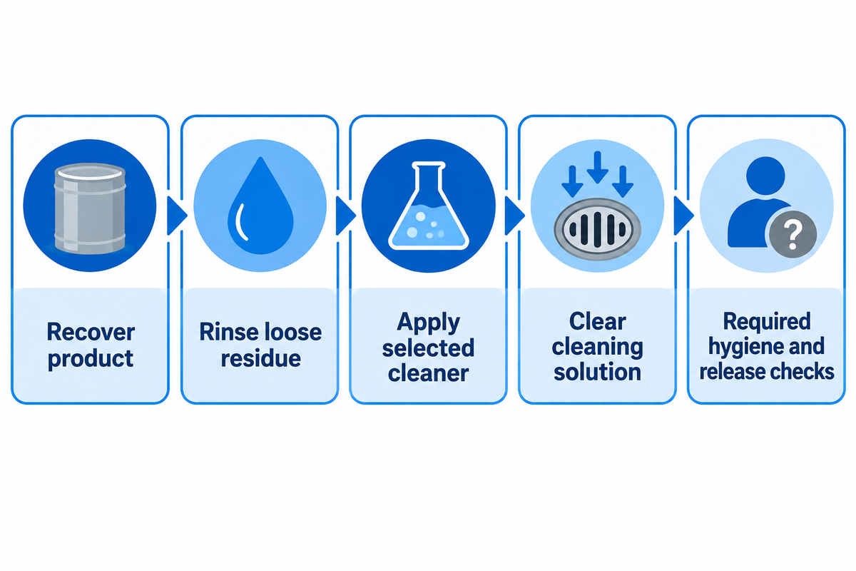
A CIP cleaning process removes soil, transports it away and prepares the contacted surfaces for the subsequent hygiene step. The sequence follows the product residue and equipment design. Pre-rinsing, detergent circulation, intermediate rinsing and a specified sanitizing stage have different functions; adding more named steps does not automatically improve cleaning.
Starting with residue, soluble beverage deposits behave differently than a dried protein film or fat or mineral scale. Cleaning chemicals must be designed in consideration of the soil and contact material. Heat can help one mechanism while making another deposit harder to remove. The combination of chemicals and mechanical action must detach and remove the soil from the surfaces and take it out of the circuit. The objective isn’t to make the tank solution stronger.
A typical CIP sequence is a useful example in teaching, as long as each step has an end-point and a reason for existing. The plant’s approved cleaning procedures determine which steps are required and how the transitions between them are regulated.
- Remove recoverable product. Separate product recovery from the cleaning duty so bulk material is not unnecessarily diluted into the cleaning stream.
- Rinse away loose residue. Direct the displaced soil to its intended destination before detergent circulation.
- Apply the selected cleaning agent. Hold the required conditions at the equipment while chemical action and flow or spray action remove attached soil.
- Clear the cleaning solution. Use the specified rinse and discharge or recovery route without uncontrolled mixing between phases.
- Complete the required hygiene and release steps. Apply the site’s specified sanitizing treatment and checks before the next production run.
Deposit removal depends on the type of deposit. Organic deposits can be addressed by an alkaline detergent, with a caustic solution if necessary. If mineral deposits are present, an acid stage may be required. Generally the cleaning agent used in CIP is to be used based on its own application instructions. CIP chemicals are to be used based on the contact requirements, concentration and the phase in which they’ll be used. The application and supplier’s label instruction govern. The alkali and acid are to be used as separate controlled phases, and a definitive separation is to be maintained between them.
The University of Florida’s cleaning and sanitizing guidance explains why increasing chemical concentration beyond recommendations can damage equipment rather than improve the result. With corroded or damaged surfaces, cleaning can be even more challenging. Chemical choice therefore belongs with seal compatibility, surface condition and the actual soil, not in an isolated purchasing decision.
Recovery introduces another variable: The introduction of reuse also creates variation in CIP solution performance. Conductivity can help follow a chosen chemistry. Soil buildup and repeated use also influence cleaning performance. Mengyuan Fan’s 2018 Ohio State research abstract reports a decline in residue-removal rate under some tested reuse conditions. That is a reason to control reuse history and solution condition, rather than assign every recovered batch a universal number of reuses.
Food and beverage manufacturing can use single-use, recovery or combined cleaning systems. Those types of CIP systems describe fluid handling. A recovery tank changes the destination of cleaning media; it does not remove the need to demonstrate suitable cleaning results. Allergen changeovers make the risk of carrying residue between duties particularly relevant.
Beverage and food cleaning arrangements need a defined endpoint for each transition. A detailed review is required to identify what’s being removed, what conditions cause removal, where the removed material goes and what ends the phase. This approach is valid for all sequences and cycles, long or short. SHENGTU’s CIP cycle selection worksheet aids in planning without treating a step count as the recipe.
CIP vs COP: Set the Cleaning Boundary
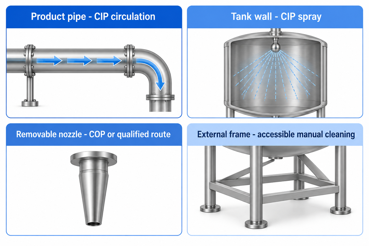
CIP cleans an installed path, while clean-out-of-place cleaning treats removed parts in suitable cleaning equipment. The direct access method gives the cleaner the opportunity to perform inspection and dismantling where required. A mixed line can require all three cleaning methods. Assign the route from surface geometry, access and demonstrated cleaning action, rather than the component’s name.
Cleaning route completions are important at interfaces. They create stopping points for verification. The interface can be between a pipe and filler, a valve in a particular position, or a removable fitting. For the cleaning action to be complete, CIP and COP responsibilities must meet at that interface and no surface must disappear between procedures.
| Surface or function | Candidate cleaning route | Deciding observation |
|---|---|---|
| Straight product pipe | CIP circulation | Included path receives suitable liquid flow and drains as designed. |
| Tank inner wall | CIP spray cleaning | Spray device reaches the surface at its required pressure and flow. |
| Tank underside obstruction | Revised spray arrangement or separate access | Coverage examination identifies a shadow behind the obstruction. |
| Valve product chamber | CIP with the designed cleaning positions, or dismantling | The procedure reaches all intended chambers and positions. |
| Removable filler nozzle | COP cleaning or a qualified installed route | Access and the validated cleaning method cover its internal detail. |
| Transfer hose | Designed CIP connection or removal | Routing, wetted coverage and drainage suit the hose and connections. |
| Gasket groove | Designed cleaning exposure or dismantled inspection | Product entrapment and the seal assembly are addressed. |
| Heat-exchanger product passage | Designed CIP circuit | Flow distribution and the fouling duty match the cleaning procedure. |
| External frame or guard | Accessible external/manual cleaning | External soil is removed without recontaminating clean product surfaces. |
These are route decisions rather than family approvals. UF’s method definitions acknowledge some cleaning arrangements as partial disassembly. The cleaning requirements belong to the assembled system and its operating procedure.
Example: A beverage processor changes from a milk-containing drink to a different product on a shared line. The transfer pipe receives the programmed circulation, but a removable filler assembly follows a separate wash procedure. Production has booked one changeover window. If the filler parts finish later than the pipe, the whole line has to wait. The plant manager schedules the two cleaning routes together. The quality team determines the relevant residue checks for both. Buying faster CIP circulation wouldn’t resolve the separate part bottleneck. Other options that could be useful are better handled parts, better COP, or a different filler cleaning assembly.
Automatic cleaning also leaves work around chemical replenishment, disconnected parts, and maintenance. Operators still have to follow the site’s training and procedures. Don’t assume that all chemical exposures disappear with automation. For a line with mixed cleaning duties, the washer selection worksheet provides an area to separate duties before a project team makes equipment selection.
Read Four CIP Variables at the Return
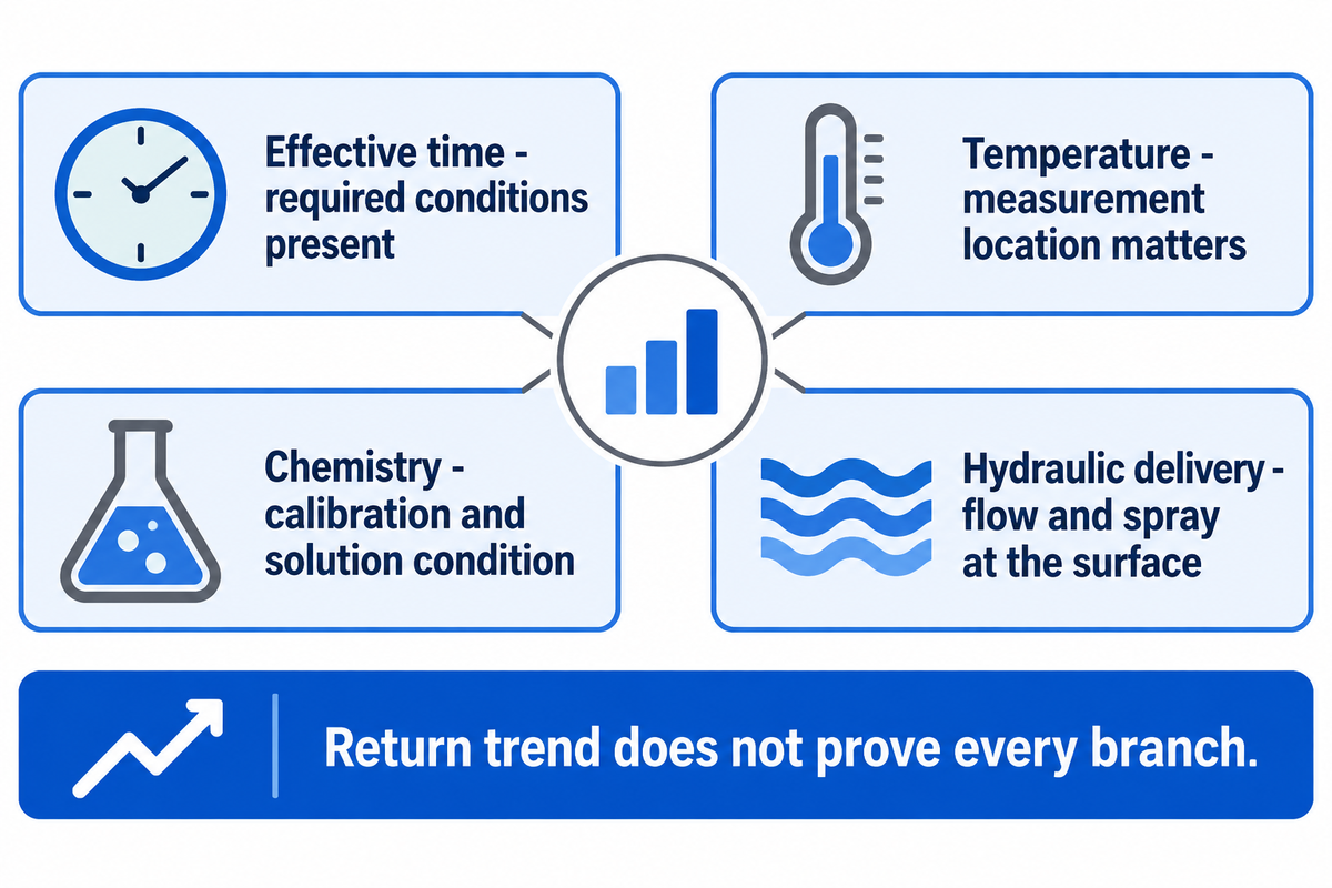
Readings on the return side help show what happens after the cleaning fluid passes through equipment. Review and assess effective contact time, temperature, chemistry, and mechanical action in conjunction with valve routing. Supply side readings remain useful, but return side data shows circuit delays, heat loss or interrupted circulation. Branches and tank spray coverage still need their own checks.
What are four factors in effective cleaning?
There are four essential factors that describe the mechanism of how soil removal occurs: time, temperature, chemical action and mechanical action. They can be identified in the instruments as factors that can be controlled, e.g. concentration, flow, spray pressure, valve positions and effective exposure time. The four factor approach is more of a starting point rather than a definitive acceptance specification.
Time counts only while the required conditions are present at the relevant location. Temperature describes the cleaning fluid at its measurement point, not every hidden surface. The conductivity of a solution is impacted by the solution’s ionic properties and temperature. Mechanical action is caused by flow and spray at a surface and not from the motor being on.
4-Signal CIP Return-Path Check
The 4-Signal CIP Return-Path Check pairs effective time, temperature, chemistry and hydraulic delivery with the actual circuit route.
| Signal | Useful record | Interpretation question |
|---|---|---|
| Effective time | Time within the required cleaning conditions | Did the intended surface receive sufficient exposure after conditions stabilized? |
| Temperature | Relevant supply and return temperature trends | Where did heating delay or temperature loss occur? |
| Chemistry | Product-specific concentration check and calibrated conductivity trend | Does this reading represent the intended cleaning agent in this solution? |
| Hydraulic delivery | Relevant flow, spray pressure and return behavior | Did liquid follow the required path with suitable mechanical action? |
Interpret conductivity using the selected cleaning chemical’s calibration, temperature compensation and solution condition. A conductivity measurement isn’t an absolute concentration measurement. The recovered cleaning fluid, e.g. detergent containing soil, raises questions that a fresh solution calibration can’t answer. Advanced CIP instrumentation is useful when it resolves such questions with an appropriate measurement.
Compare pipes and vessels separately. Process engineer Andrew Klosinski’s brewery CIP discussion explains that spray devices operate within manufacturer-defined pressure and flow requirements. Poor tank drainage can flood surfaces and reduce spray impact. Pipe cleaning instead needs appropriate hydraulic action in the intended liquid-filled route. “More flow” is too vague to distinguish these problems.
Example: use an assumed internal pipe diameter of 50 mm and a mean liquid velocity of 1.5 m/s. The area is π × 0.05² ÷ 4 = 0.001963 m². Multiplying by 1.5 m/s and 3,600 s/h gives approximately 10.6 m³/h. Oklahoma State lists 1.5 m/s as a general pipeline rule of thumb. The calculation converts velocity to flow; pipe geometry, fluid properties, pressure losses and actual cleaning performance still govern the application.
A branch can remain closed while a parallel path satisfies the return flow. The aggregate trend can look stable in that situation. Valve state records and a route check can connect the measurement to the branch being cleaned. A vessel spray shadow creates a different problem: the return can be satisfactory while a protected area receives inadequate impact.
Use SHENGTU’s CIP circuit data sheet to provide actual paths, equipment and utilities. That is a more useful input for circuit design than a supply-flow number detached from pipe dimensions or tank cleaning devices.
A 50 mm internal bore needs about 10.6 m³/h to reach the example velocity of 1.5 m/s. A common return meter measures the combined returning liquid; branch routing and spray-device performance remain separate engineering checks. Match the values recorded with the location and the verification question they answered.
Investigate CIP Cleaning Failures in the Right Order
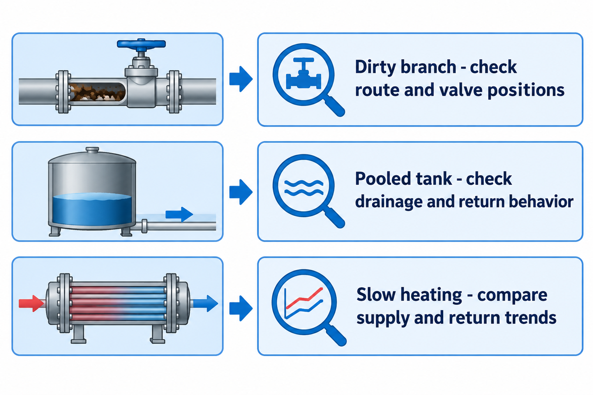
Investigate a failed CIP by identifying the residue and affected location, and determining route, delivery and exposure prior to changing chemistry. Compare the failed run with a relevant accepted run. The investigation must connect the controller status record and the mechanism of cleaning with the surface in contact with the residue.
Begin with nonintrusive records: product history, hold time before cleaning, selected recipe, circuit identity, alarms and trend timing. A longer dirty hold or a different soil load may account for the absence of expected results from cleaning steps. Keep the quality decision and the maintenance diagnosis separate. An unresolved result shouldn’t be an informal production release.
Prior to opening or dismantling equipment: authorized personnel must follow the applicable site isolation procedure for moving equipment and stored chemical, thermal, hydraulic or pneumatic energy. A control-screen stop isn’t energy isolation. OSHA 1910.147 addresses servicing and maintenance where unexpected startup or released energy may injure employees. Reading trends and carrying out intrusive inspection are different activities.
| Observed symptom | First evidence to review | Next diagnostic direction |
|---|---|---|
| Return heats slowly | Supply/return temperature trends and phase timing | Separate heating capacity, heat loss and circuit warm-up. |
| Flow fluctuates | Pump, valve and return trends for the selected route | Investigate delivery interruption and gas/liquid return conditions. |
| Tank retains liquid | Liquid level, drain route and return behavior | Examine whether accumulation reduces spray action. |
| One branch remains dirty | As-built route and valve positions | Check branch inclusion before increasing the main-loop recipe. |
| Residue remains behind an obstruction | Spray arrangement and coverage examination | Address the shadowed surface or its separate cleaning route. |
| Concentration-related trend drifts | Chemical identity, calibration, temperature and reuse history | Separate measurement error, dilution and solution-condition changes. |
| Mineral deposits recur | Water quality, soil identity and chemical program | Review deposit chemistry and compatible treatment. |
| General hygiene passes but allergen result fails | Target-specific sampling and analytical method | Investigate the relevant residue and hard-to-clean locations. |
| Recontamination follows cleaning | Part handling, reassembly and surrounding cleaning activities | Protect cleaned food contact surfaces through the release window. |
The order prevents a costly mistake: compensating for a missing route with a harsher chemical process. If a closed branch receives no cleaning fluid, increasing the main-loop cleaning temperature won’t provide contact in that branch. If liquid is pooled in a vessel, an extended timer may consume even more time, and the spray problem remains unsolved.
Example: a shared sauce line completes its usual recipe, but residue appears repeatedly at one filler connection. The return temperature record matches an accepted run. Increasing the detergent dose would change a condition that already looks consistent, and the repeated location indicates a connection. The investigation would take into account the as-built valve route, the assembled fitting and the separate part procedure. If product is trapped, the access or geometry problem would be addressed. A different finding could redirect it toward cleaning fluids or exposure. The quality team retains the line under its release procedure. The engineering team determines the cause and effect relationship.
After the cause is corrected, record the changed condition and repeat the relevant effectiveness checks. Otherwise, the next crew inherits a long recipe without an explanation. Repeatable cleaning requires control of the cause, not just repetition of the controller sequence.
What Cleaning Records Can and Cannot Prove
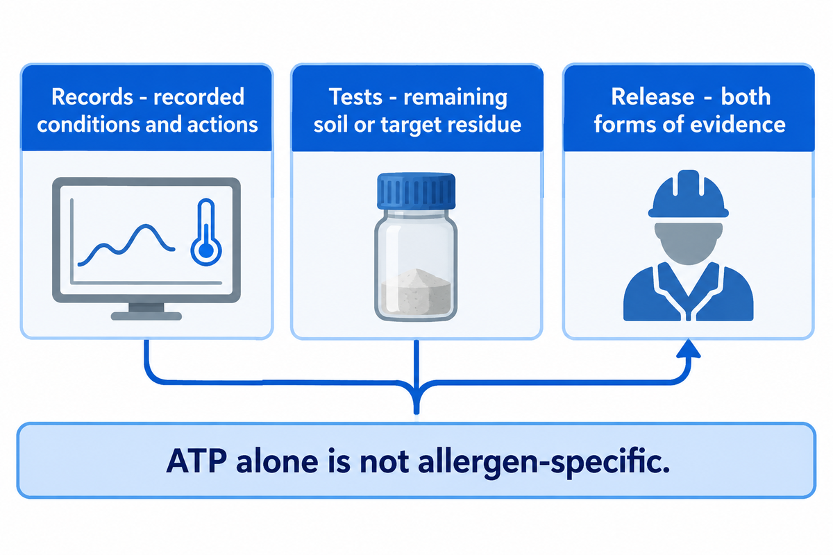
Cleaning records provide evidence that a procedure has been documented, recorded, and performed, and that the recorded conditions and actions correspond to the intended requirements. Inspection and suitable analytical tests assess the remaining soil or target residue. Both forms of evidence are to be taken into account for making a production release decision. The method is to be appropriately addressed to the product, surface and risk being examined. One test can’t respond to all hygiene questions.
Keep the question linked to the result. A trend of temperatures answers a process question. A visual examination addresses accessible soil. A hygiene rapid test provides its specified indicator. Testing for the presence of allergens in a defined matrix of the sample addresses the target residue. Again, other purposes and methods of sampling, especially of the microbiological nature, apply.
“End users must determine their own acceptance criteria for equipment cleanliness.”
For example, the coverage of a spray test may reveal an area that isn’t covered by the cleaning liquid. This result addresses the effectiveness of the geometry of the equipment. A test of target residue raises the question as to whether the cleaning procedure removed the soil of concern.
The FDA’s seafood allergen-cleaning guidance, Appendix 10, advises against ATP swabs alone for allergen-cleaning verification because ATP is not allergen-specific. The guidance covers several methods, and while the recommendations are not binding, they describe each method’s difference from the others and offer examples of controls. Those do not establish a universal recipe for allergen cleaning for food and beverage facilities. Food and beverage facilities must adjust the method to match the residue and the equipment on which it is used.
Useful cleaning protocols define the route and responsible people. A run record links the result to the product previously processed, the recipe revision, circuit, instruments, deviations and disposition. The associated sampling plan identifies the relevant residue, location and method. Without a defined location, a cleaning result may not be interpretable; a trend without a circuit may belong to the wrong path of cleaning.
Cleaning validation in engineering means showing that the defined method works for the application. Routine verification checks its continuing execution and result. Legal duties require their own scope assessment: 21 CFR 117.160(c) excludes food-allergen and sanitation controls from that section’s validation requirement. That narrow legal distinction does not remove the practical need for effective cleaning and appropriate checks.
Certain changes, for example, a different protein-rich product, longer production campaign, different seal or pipe branch, or new chemical, may require reevaluation of the method and may therefore affect the accepted cleaning. The plant’s quality and engineering teams should evaluate changes prior to relying on old cleaning records.
For procurement, request records that connect the offered controls to the installed application: an identifiable circuit, usable trends and agreed test results. A certificate for a component answers a different question from the plant’s acceptance of a cleaning procedure. Be sure the project scope doesn’t lead either party to expect a certificate in lieu of commissioning evidence.
Compare Cost per Accepted Cleaning Cycle
Compare CIP operations by the cost of an accepted cleaning event, including repeated attempts. Use the same production duty cycle, period and currency for each. Count water, chemicals, heat, labor and waste. Oklahoma State University identifies energy, water and cleaning chemicals as CIP expense categories; the example below adds plant-specific operating assumptions. Add lost production contribution only for cleaning time that actually occupies a constrained, saleable production window.
The denominator makes a difference. A cleaning attempt that needs repeating has consumed resources without releasing the line. Dividing cost by programmed cycles can reward a short recipe that results in a high rework rate. Both production and finance, therefore, need the attempt count as well as the number of accepted events over a common period.
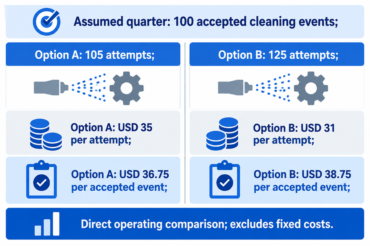
Example: assumed inputs for the same quarter and 100 accepted cleaning events. Option A required 105 attempts; Option B required 125. Direct cost included water, chemicals, heat, labor and waste. Purchase price, maintenance and fixed overhead are excluded from this operating comparison.
| Assumed input or calculated result | Option A | Option B |
|---|---|---|
| Accepted events in the quarter | 100 events | 100 events |
| Total attempts | 105 attempts | 125 attempts |
| Repeat attempts | 5 attempts | 25 attempts |
| Direct operating cost per attempt | USD 35 | USD 31 |
| Total direct operating cost | USD 3,675 | USD 3,875 |
| Occupied time per attempt | 75 min | 65 min |
| Total occupied cleaning time | 131.25 h | 135.42 h |
| Direct cost per accepted event | USD 36.75 | USD 38.75 |
| Conditional lost-contribution rate | USD 80/h | USD 80/h |
| Conditional operating cost plus lost contribution | USD 14,175.00 | USD 14,708.33 |
| Conditional total per accepted event | USD 141.75 | USD 147.08 |
Direct cost per accepted event is total attempt cost divided by accepted events. For A: 105 × USD 35 ÷ 100 = USD 36.75. For B: 125 × USD 31 ÷ 100 = USD 38.75. The lower attempt price loses its advantage because more attempts are required.
For the contribution column, assume every occupied cleaning hour displaces production on the limiting line, with queued customer demand and no schedule overlap. At USD 80/h of contribution after avoided variable production costs, A’s calculation is [USD 3,675 + (105 × 75 ÷ 60 × USD 80)] ÷ 100 = USD 141.75. B gives USD 147.08 using its unrounded 135.4167 h. The rate is contribution, not sales revenue.
If cleaning runs inside an otherwise idle period, use zero lost contribution for those hours. If only part of the cleaning time delays production, use only that avoidable lost time. A change of schedule can therefore affect the financial outcome without changing water and/or chemicals used. That is why the plant manager and finance team should agree on the bottleneck before a payback claim is made.
Under the stated assumptions, Option A costs USD 36.75 per accepted event before lost contribution, compared with USD 38.75 for Option B. Including the fully constrained production window gives USD 141.75 and USD 147.08. Before comparing the return on the project, replace the example inputs with one plant’s accepted event ledger.
Integration and Utility Limits Before Commissioning
Installing a CIP system requires the necessary supply, heating, return and disposal capacity to support the cleaning schedule. Shared utilities can restrict simultaneous circuits even if each circuit works independently. Commissioning should link the installed route to the agreed cleaning duties, with supplier delivery evidence and plant quality acceptance responsibility clearly defined.
CIP technologies are useful when their controls and measurements address the installed duty. CIP systems are used in various process arrangements, so compare the cleaning functions and interfaces for each and not base it on a technology label.
Account for the simultaneous demand, not just the number of tanks, on the CIP skid. The pump must be able to deliver through the installed pressure losses. The spray device must receive the specified conditions. The return system must remove the liquid. Heating and fresh water supply may have other users. Wastewater handling can impose another constraint at discharge.
Food Engineering’s process-integration discussion connects CIP decisions to the production process and utility constraints. Treating the skid as a standalone purchase can postpone those questions until installation, when changing pipe routes or heating capacity is more disruptive.
| Shared constraint | Effect on the cleaning window | Commissioning evidence |
|---|---|---|
| Supply pump and pipe losses | Required delivery may fall when the installed route is connected. | Relevant flow and pressure at the actual duty. |
| Tank spray demand | Coverage changes outside the device’s required conditions. | Spray-device requirements and coverage examination. |
| Return removal and drainage | Accumulation can reduce cleaning action and delay phase changes. | Return behavior and vessel level over the cycle. |
| Heating or steam availability | Warm-up can delay effective exposure. | Supply/return temperature trends under simultaneous demand. |
| Fresh-water availability | Concurrent rinsing can compete with other consumers. | Measured demand during the planned schedule. |
| Wastewater and discharge route | Discharge restrictions can extend turnover. | Agreed discharge conditions and capacity. |
| Separate-part cleaning | Production waits for the last required cleaning route. | Part turnaround and reassembly sequence. |
| Sampling and release | Completed cleaning can still await a disposition. | Assigned methods, responsibilities and release timing. |
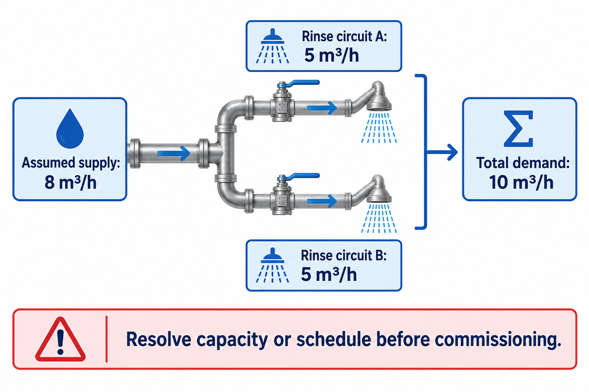
Example: an assumed shared water supply can deliver 8 m³/h during cleaning. Two rinse circuits each require 5 m³/h simultaneously. The total demand is 10 m³/h, which exceeds the supply. A larger control screen or additional recovery tank wouldn’t resolve the demand. Changes to the project schedule, the supply, or other demonstrated arrangements are required. Before promising both circuits can be operated within the same cleaning window, the actual demand should be tested to ensure it can be satisfied simultaneously.
The handoff should include the as-built piping, routes, and identifications of instruments; recipe control and access; behavior of alarms; agreed-upon test conditions; drain destinations; and the equipment controls and demonstration by the supplier. The plant’s quality team owns release for production. 3-A Accepted Practice 605-05 is an installation-and-CIP reference to discuss where applicable, rather than a substitute for the project’s agreed scope.
SHENGTU’s food-processing equipment and project background describes owned manufacturing bases together with selected partner factories for specialized or supplementary machines. Assign the responsible supplier for each cleaning interface in the project brief. Certificates and test documents should be for the actual model, configuration and destination.
A shared 8 m³/h water supply can’t simultaneously deliver two assumed 5 m³/h rinse duties. Resolve that schedule or capacity gap before commissioning promises are fixed. The same demand check also applies to heating, return removal and discharge because spare capacity in one service doesn’t create capacity in another service.
Key takeaway
Match the cleaning boundary, measured delivery and release criteria before comparing cycle speed. A useful CIP proposal connects all three to the installed production line.
Frequently Asked Questions
What does CIP stand for?
CIP stands for clean-in-place.
The term describes cleaning an included equipment path without routine dismantling of that path. Pumps circulate selected cleaning fluids, or spray devices apply them to surfaces. The complete duty includes the equipment, its supply and return connections, and any valve positions needed for cleaning. Separate parts or external surfaces can still need their own cleaning method.
What is a three-step CIP process?
A three-step CIP process generally groups the duty into a rinse, a cleaning wash and a final rinse.
Counting conventions differ between suppliers, so compare the actual phase functions. Product recovery, acid treatment or sanitization may be separate phases in another procedure. A three-step label doesn’t establish chemical settings or acceptance criteria. The appropriate cleaning phase sequence follows the soil, equipment design, chemical instructions and required result for the next production run.
How long does a CIP cycle take?
CIP cycle time is the total of its filling, heating, effective cleaning, rinsing, draining and required treatment phases.
Use the approved recipe and measured circuit trends to establish the duration for a particular line. A supply-tank timer can include time before the distant equipment reaches its required conditions. Separate-part cleaning and release testing may extend the full changeover even after circulation ends. Compare accepted changeover time as well as the controller’s nominal cycle duration.
What is a CIP skid?
A CIP skid is a packaged assembly of cleaning-fluid handling and control equipment.
CIP skids combine cleaning-fluid handling and controls. The complete duty also includes connected process equipment, pipework and the installed return path.
What chemical is used for CIP?
CIP uses a cleaning agent selected for the soil and compatible with the equipment, often from alkaline or acid detergent families.
Alkaline chemical cleaning agents can address organic residues, while acid programs can address mineral deposits. Sanitizing agents perform a different task after suitable soil removal. Product-contact materials, seals, water quality and the next product all affect the chemical program. Use the selected product’s label and application instructions; more concentrated chemistry isn’t a general cure for inadequate flow, poor spray coverage or trapped residue. A chemical program also needs controlled storage, dosing and separation between incompatible phases. Recovered solutions need an identified duty and suitable condition checks before reuse. When the product changes, the existing chemical program needs review against the new soil and next-product requirements. Follow the established site procedure when handling or changing chemicals, rather than copying a concentration from an unrelated cycle example.
Turn the cleaning duty into a defined project scope
Bring the product family, circuit drawing, separate-part duties and cleaning window to the equipment discussion. SHENGTU can use that brief to discuss cleaning and CIP integration with your processing line.
This document describes cleaning principles for food processing, and cites university, original research and other technical sources. Calculated illustrative examples employ the assumptions provided. The procedures defined for the site govern operating values. Release for production is based on agreed acceptance criteria.
References & Sources
- What Is Clean-in-Place (CIP)? Oklahoma State University, Timothy J. Bowser, FAPC-251, 2023.
- Basic Elements of Equipment Cleaning and Sanitizing in Food Processing and Handling Operations University of Florida Institute of Food and Agricultural Sciences, Ronald H. Schmidt.
- Fundamental Understandings and Optimization Strategies of in-place cleaning Mengyuan Fan, Ohio State University, 2018; original research abstract.
- Optimizing Brewery CIP Systems, Part 2 Food Engineering, Andrew Klosinski, 2025.
- 29 CFR 1910.147: Control of Hazardous Energy Occupational Safety and Health Administration.
- Appendix 10: Cleaning and Sanitation for the Control of Allergens U.S. Food and Drug Administration, 2019, A10-1–4.
- 21 CFR 117.160: Validation Electronic Code of Federal Regulations, U.S. Food and Drug Administration.
- Make CIP an Integral Part of Your Process Food Engineering, Wayne Labs, 2023.
- 3-A Accepted Practice 605-05 3-A Sanitary Standards, public installation-and-CIP catalogue entry.
![Meat / Poultry / Prepared: Plant Planning Guide [2026]](https://shengtumachinery.com/wp-content/uploads/2026/10/meat-poultry-prepared-processing-guide-featured-768x512.png)