
Get in touch with Shengtu Bufan Company

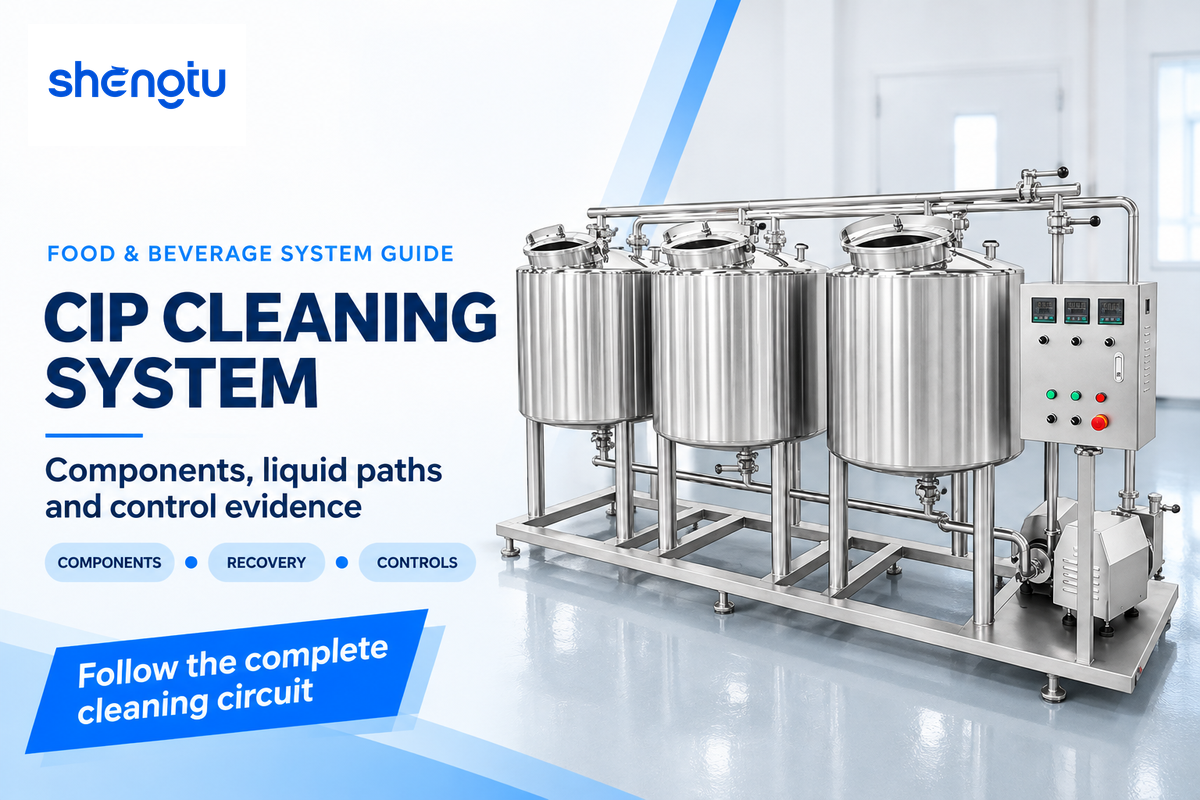
A CIP Cleaning System uses a defined liquid path to clean the included interior surfaces of process equipment. Tanks, pumps, heaters, chemical dosing, valves, and controls work in unison to make up the system. Following the liquid path takes the operator through the equipment’s function and connects its operating conditions to the records and checks needed before food production resumes.
By Cherry, SHENGTU · Updated October 2026
A complete CIP system connects the cleaning supply, process circuit and return destination. Its configuration determines how cleaning fluids move, which functions operators perform, and what the plant can record about each cleaning cycle.
Key points
- Separate circulation during a wash from recovery for a later wash.
- Compare automation by the functions it performs and records it retains.
- Calculate freshwater use across the same boundary, including makeup and purge.
- Plan the process-equipment interfaces alongside the cleaning skid.
Food and beverage industries use CIP technologies, as do pharmaceutical industries, although their acceptance requirements differ. This reference guide covers food and beverage processing systems. A more thorough discussion on method selection and fault diagnosis is covered in our companion guide on cleaning methods and CIP fault checks.
How a CIP Cleaning System Connects Equipment and Controls
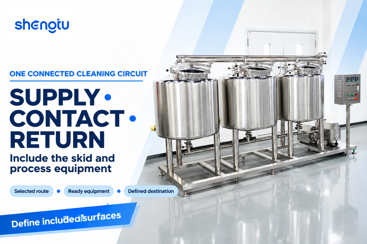
A clean-in-place system directs a prepared liquid to a surface assigned to a cleaning circuit, provides the required action, and conveys the liquid to its next destination. The circuit includes the connections between the skid and the process equipment. A suitable system description is provided by following the supply path, contact surfaces and the return path together.
With a selected tank, the supply pump provides liquid to the heater and distribution path. In the process lines or vessel, flow, flooding or spray contact removes soil. The return path returns the liquid to the system, to a recovery tank, or to drain. The destination may vary during different phases.
The controller initiates the movement. It needs information from the process equipment and its own instruments. The right vessel has to be available, the chosen route has to be clear, and the return has to have a destination. A cleaning skid and a production line combine to form one circuit at these interfaces.
“Record CIP operating variables to verify cleaning and sanitizing.”
Timothy J. Bowser, Oklahoma State University Extension, FAPC-251
Sanitary process equipment needs a defined boundary for cleaning. In its guidance, 3-A describes components that users disassemble for manual cleaning or clean-out-of-place. A complete circuit list identifies those components along with the surfaces that are cleaned when the components are assembled.
7 CIP System Components and Their Jobs
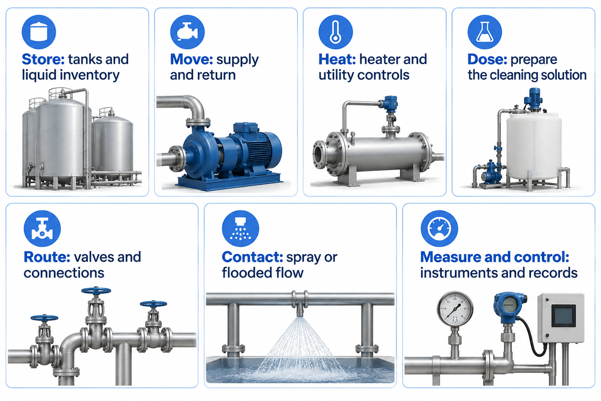
Functional groups make a CIP specification easier to read and include storage, liquid movement, heat, chemical dosing, routing, contact devices, and instruments with controls. The groups organize the explanation. An installed system may incorporate several functions in one assembly. The most important element is how each function serves the specified circuit and what operating conditions apply to that circuit.
| Function | Typical equipment | Connection to the process |
|---|---|---|
| 1. Store | CIP tank, accumulation vessel, recovery tanks | Provide usable liquid inventory and a defined destination for recovered phases. |
| 2. Move | Supply pump and suitable return arrangement | Deliver the circuit duty and remove returning liquid at a compatible rate. |
| 3. Heat | Heat exchanger, heater and utility controls | Bring the liquid to the required condition while accounting for circuit heat loss. |
| 4. Dose | Chemical feed equipment and preparation controls | Prepare and adjust the specified cleaning solution. |
| 5. Route | Valves, manifolds, transfer panels, pipe and fitting connections | Select the intended supply and return paths and isolate incompatible duties. |
| 6. Contact | Spray devices or a flooded flow path | Apply liquid action to the internal surfaces the circuit is designed to clean. |
| 7. Measure and control | Instruments, controller, operator interface and recorder | Measure conditions, run the sequence, handle exceptions and document the cleaning. |
How does a CIP system work?
A CIP system is responsible for preparing a cleaning fluid, sending it through a selected equipment circuit, and managing the return. Feedback instruments supply information, while operators or automatic controls perform the functions needed for each phase of the program.
For example, cleaning the interior surfaces of a vessel may require spray coverage around the agitator. In contrast, a plate pasteurizer has flow passages that are closed and integrated within the equipment. Both types of equipment can be connected to CIP equipment, but the required flow and contact arrangements depend on the equipment being cleaned.
Returns should also receive the same focus as supplies. CIP fluid delivered in excess of the available return capacity can cause undesirable buildup. Food Engineering’s equipment report provides an example of integrating the supply and return process using an example in the beverage industry. A more helpful specification states the circuit’s actual duty rather than depending on the nameplate of the pump.
Single-Use and Recovery CIP: Follow the Liquid
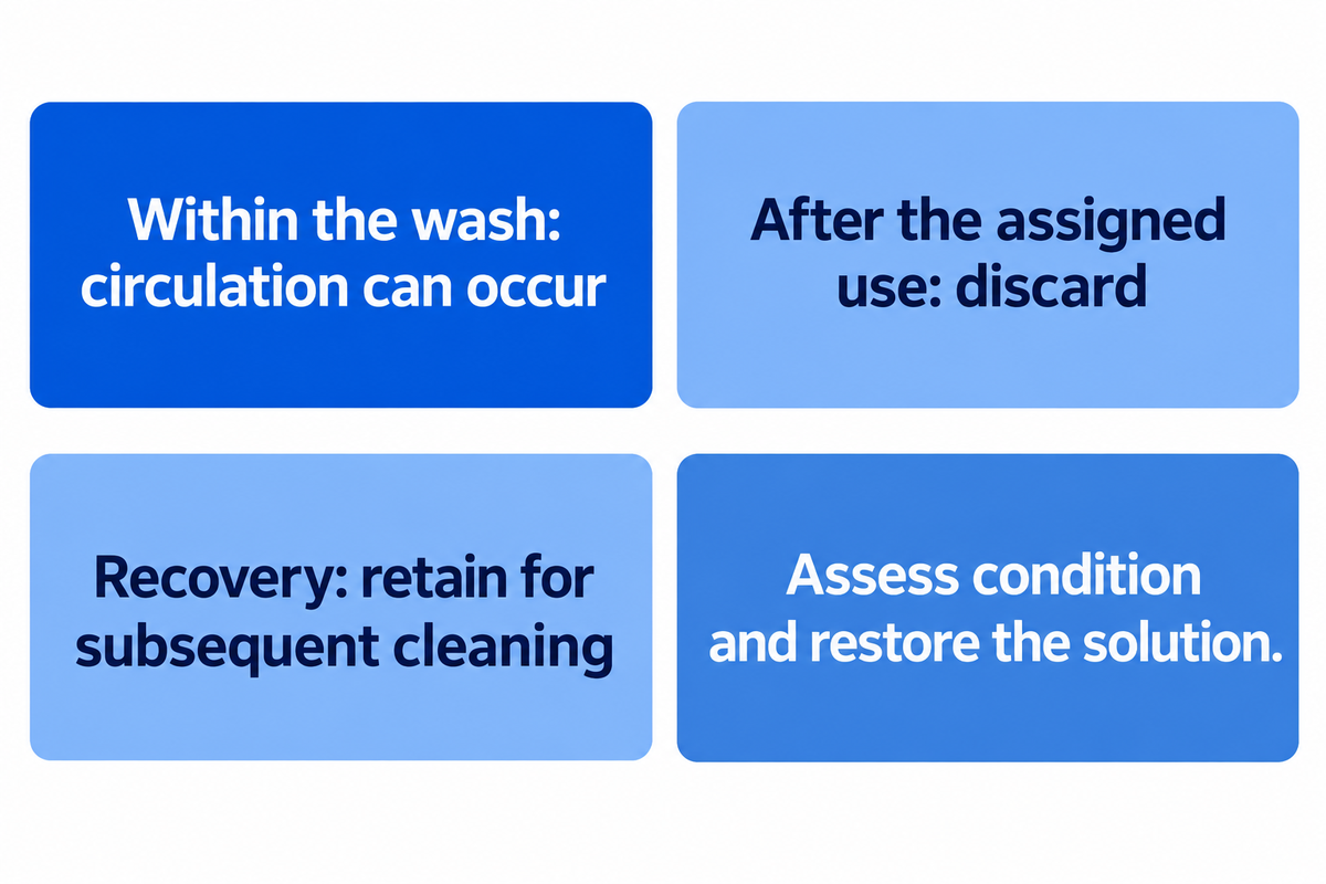
Single-use and recovery arrangements differ in the treatment of cleansing liquids. In single-use arrangements the cleansing liquid is disposed of after its use, while in recovery arrangements, the cleansing liquids are retained for later use (subsequent cleaning). Whether a liquid is circulated within the cycle is different. It’s possible for a liquid to be circuited within a wash and be discarded at the end of that wash.
How does single-use CIP differ from recovery CIP?
The most explicit description of system operation refers to the liquid path and the time boundary. Once through (or non-recirculated) liquid passes through a piece of equipment and is then removed from the system. Recirculated liquid passes through the same piece of equipment, and then returns to the system to begin the process again.
Recovered liquid is saved for a later use. The terminology used to describe systems by suppliers can vary, and so the three descriptions provide the most explicit information regarding the proposed operating system.
In Bowser’s technical article, a recirculation tank is classified as a single-use system component in a system where storage for later cleaning cycles is differentiated. Recovery also creates a liquid-management job: classify the return, choose the tank and assess the condition of the return, and restore for the next cleaning cycle.
Discard after the assigned use
Fresh preparation simplifies the between-cycle solution inventory. Water, chemicals and discharge still depend on the actual cleaning program.
Retain for subsequent cleaning
Storage can preserve useful liquid, residual heat and chemicals. Return selection, solution condition, makeup and tank cleaning become part of the operating plan.
Recovery boundaries also follow the products and their contamination risks. FDA’s seafood allergen guidance states that reused cleaning solutions can recontaminate surfaces. Their guidance pertains to the particular processing situation, but the underlying question is useful anywhere products share a cleaning system: which returns are adequate for the next assigned duty?
In a 2022 reuse study on cleaning agents, Fan, Kim and Heldman noted changes in active alkali and cleaning effectiveness in their bench and pilot studies. Their results also suggest assessing a returned caustic solution. Reuse limits also apply to the demonstrated product, chemistry and process combination.
CIP Cycles: What Changes Between the Steps
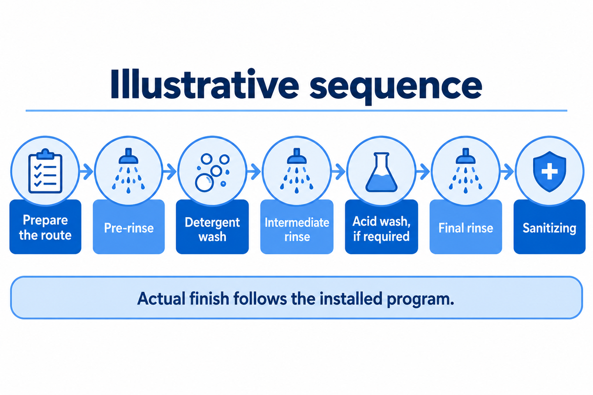
The CIP cleaning process modifies more than the liquid in the supply tank. Each phase serves a purpose and has a route and condition for advancement. Pre-rinsing removes loose residue, a detergent wash attacks attached soil, and subsequent rinsing washes away displaced soil and cleaning chemicals. Sanitizing, if present, serves a separate microbial control function.
- Establish the route. Identify the equipment, its available status, the selected cleaning program and the return destination.
- Remove and wash the soil. Apply the appropriate rinsing and washing phases, including a caustic wash or other chemistry selected for the duty.
- Complete the assigned finish. Perform the specified rinse, sanitizing, draining or drying actions, then evaluate the cycle and its associated checks.
Diagrams published by various sources tend to combine or split these functions in different ways. OSU gives a custom-designed cycle example, while UF gives a simpler rinse-clean-rinse-sanitize sequence. The variation in the number of steps reflects the teaching boundary and the function of the application. A typical CIP diagram is a methodological way to understand the sequence, and an installed program defines the actual transitions.
For timing the various cleaning steps, one needs to define a starting point. Bowser describes contact time while required conditions are satisfied. Heating up a long supply route, filling and attaining the required concentration can precede contact time. Distinguishing preparation time from in-condition cleaning time is useful in comparing the time for the purpose of production.
What are the 7 steps of the clean-in-place (CIP) process?
An illustrative seven-step sequence is the preparation of the route, pre-rinse, detergent wash, intermediate rinse, acid wash (if required), final rinse, and sanitizing. Later phases and actions are determined by the equipment, soil and sanitizing instructions, as defined by the installed program.
Different programs may use a typical cip sequence, where liquid preparation is separated from heating. Some programs include a post-sanitizing rinse and drying, combine rinse operations, or may incorporate other differences. A useful recipe describes the purpose, liquid destination and completion condition for each phase.
The chemicals used in CIP can influence the outcome, as well. For instance, a sanitizing solution that uses peracetic acid is used according to its applicable label instructions and the site’s cleaning program. The final-rinse arrangement, drainage and holding condition should also be included in that program.
Manual, Semi-Automatic and Automatic CIP Controls
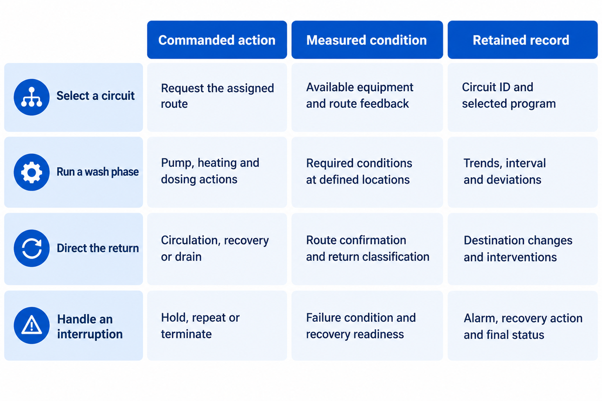
Automation specifies by whom and how functions are performed, as well as how the system reacts to conditions. In a fully manual operation, operators can use instruments and documents. Semi-automatic operation combines operator tasks with programmed phases; a fully automatic sequence can coordinate dosing, routing and recording.
What changes when a CIP system is automated?
Automated CIP replaces operator action with a program, feedback and recorded events. The program defines how the system responds to interruptions and phase transitions. Comparing programs gives insights into functions that a particular control package will perform during automated cleaning.
The 2023 Food Engineering interviews explain communication between cleaning system and process equipment, such as status of equipment readiness, operation of valves and agitators. When equipment is supplied by a third party, these details are important. For a phase to be selected to proceed, one controller must transmit the information needed to the other.
| Operating function | Commanded action | Measured condition | Retained record |
|---|---|---|---|
| Select a circuit | Request the assigned route. | Available equipment and applicable route feedback. | Circuit ID, selected program and confirmation. |
| Run a wash phase | Start the configured pump, heating and dosing actions. | Required operating conditions at defined locations. | Actual trends, in-condition interval and deviations. |
| Direct the return | Select circulation, recovery or drain. | Applicable route confirmation and return classification. | Destination changes and operator interventions. |
| Handle an interruption | Hold, repeat or terminate according to the procedure. | Failure condition and readiness for the authorized recovery action. | Alarm, interruption, recovery action and final status. |
This table is a comparison method used by a buyer. Each column addresses a different question regarding execution. The plant connects the run to the applicable cleaning-effectiveness checks and release decisions.
The benefits of CIP automation include repeatable activities and less routine exposure to chemicals; operators still need an appropriate cleaning program. The automation proposal is more useful when it identifies the operator actions that are still required, and the behavior after a power or signal failure.
Why Dairy, Beverage and Sauce Circuits Need Different Recipes
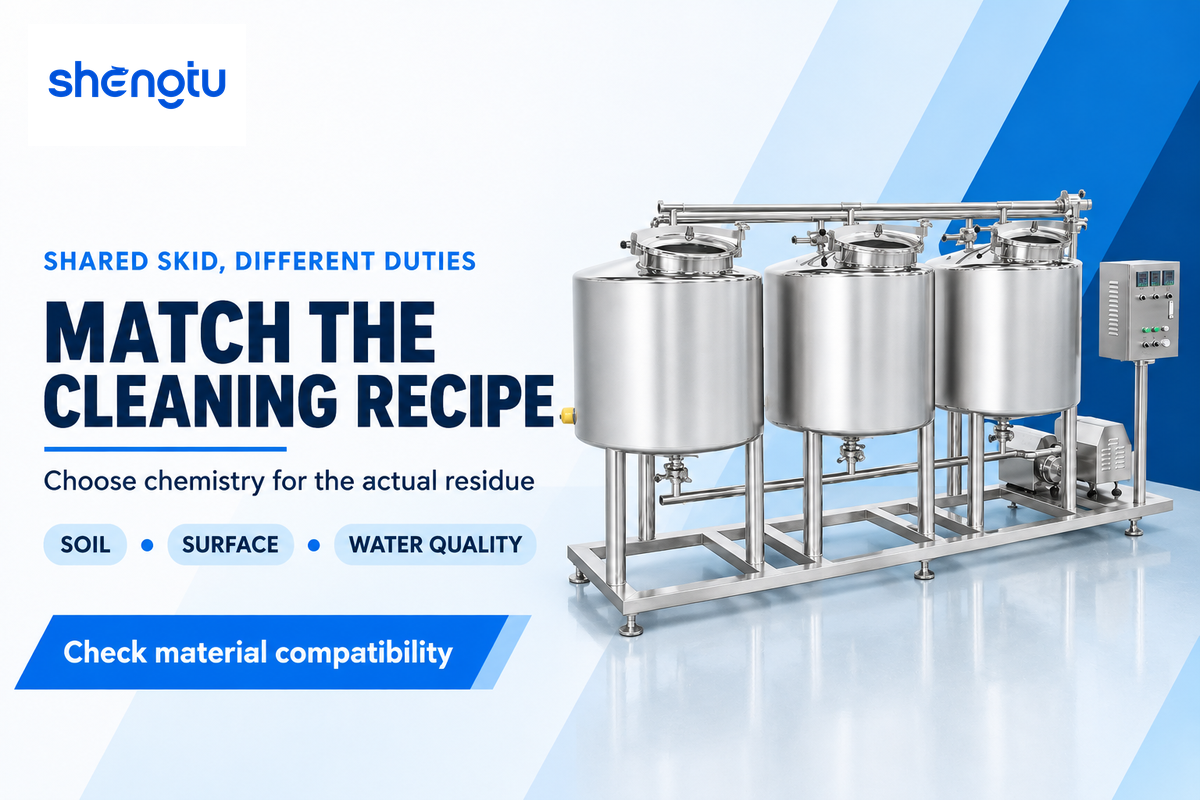
Cleaning agents and operating conditions follow the soil, the surface and equipment being cleaned. Sugars, fats and proteins and mineral deposits respond differently to water and detergent chemistry. Heating or drying during production may affect the tenacity of residue adhering to surfaces. A shared skid may require several different cleaning programs.
In dairy plants, protein, fat and mineral soils from dairy products may be retained in a milk processing line. Deposits that have been heat treated may be different from fresh residues. A line for preparation of tomato and chili sauces may retain various types of viscous residues, oils and particles. Processing and ingredients define the nature of residue better than industry classification.
UF’s equipment cleaning directions state alkaline cleaning agents can clean protein and fat soils, and acid cleaners can address mineral scale deposits. Sodium hydroxide is an alkaline cleaner, and cleaning products used in food processing can be formulated with wetting agents, sequestrants or enzymes for a particular soil and water quality.
Material compatibility is usually assessed along the complete contact surface of the part (seals, liners, elastomers and other non-metallic parts). The cleaning system specification connects the required chemistry to the materials and the equipment manufacturer’s operating instructions. More aggressive caustic chemicals can create a different compatibility problem without improving the desired cleanliness level.
What is a CIP cleaning agent?
A CIP cleaning agent is a chemical formulation to remove soil from a piece of equipment. It may contain ingredients to wet, dissolve, emulsify, disperse or otherwise remove the residue, or manage minerals in the water. The type of soil, the material of the surface to be cleaned, the quality of the water used, and the operating conditions of the equipment dictate the choice of cleaning agent to be used.
Cleaning mechanisms can vary based on the type of deposit (protein vs. mineral) and the formulation of the cleaner (commercial detergents can contain multiple active ingredients for the task). A chemical supplier and plant team can match the selected agent to the actual circuit and the desired cleanliness level.
For food and dairy duties, hygiene relies on both proper cleaning and the assigned microbial control program. Removing soil makes a surface ready for the assigned sanitizing agent; the procedure used to sanitize also requires adequate contact and conditions. Allergen removal also raises the question of control of residue. That’s the reason an effective cleaning program starts with the actual product and equipment.
What a Useful CIP Cycle Record Should Contain
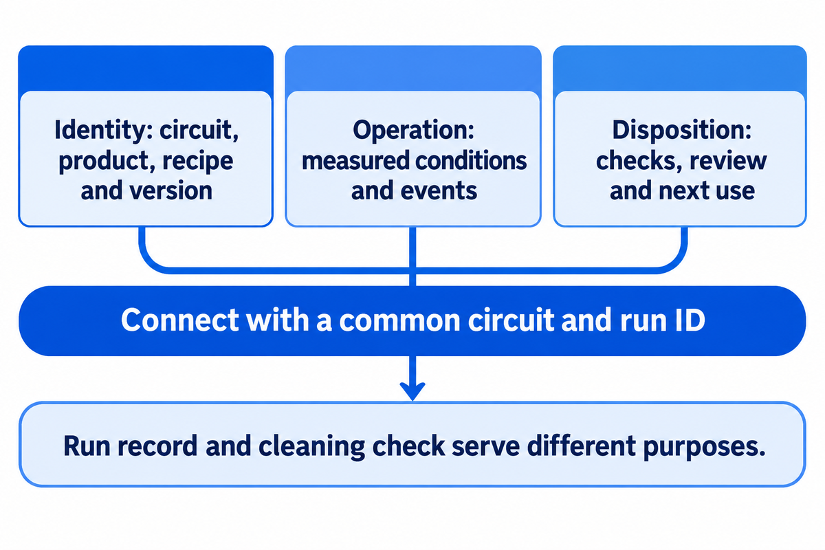
A cycle record that’s useful to the plant allows it to reconstruct what was cleaned, which program was run, what conditions were met and how exceptions were handled. It also relates the program to specified cleaning checks and final disposition of the equipment. The format of the record is in line with the plant’s food safety plan, responsibilities and requirements.
A useful record has three interconnected parts. The identity part names the circuit, equipment, product, recipe and version and time stamps. The operating part captures the measured conditions and events that describe the phase. The disposition part relates the cleaning check results, review and decision about the next use of the equipment.
Food Engineering describes a soup plant case where an operator confirmed completion of a production run before automated CIP started. Alarms pointed to deviations and the plant retained records of cleanings. The case illustrates the relationship between process status, operator action, and a documented run of traceable cleaning.
Interpretation of instruments should be part of the design of the records. The measurement of concentration can be followed using a conductivity sensor and can also be used to differentiate between liquids. A technical note of Endress+Hauser describes the chemical-specific calibration relationship and temperature compensation. During a measurement, the conductivity of a defined solution varies with its temperature. To help distinguish a changed solution from a changed measurement condition, a record retains the measurement together with the relevant calibration context.
The records of a run and of a cleaning check serve different purposes. A run record describes the completion of a process step while an inspection or analytical result serves to determine the outcome of a cleaning step. They’re referred to by a common circuit and run ID and thus remain associated. Where a rinse-water check is required, the final rinse water result also is associated with the same circuit and run ID. The definition of the required evidence, acceptance criteria, and reviewer is prescribed.
During system start-ups, define who has ownership of changes to recipes, maintenance of instruments, review of alarms and access to storage. Each interruption record links the associated alarm, the operator’s response and the repeated phase. These records give a sequence of events that helps determine how equipment should be handled prior to the next production run.
Compare Recovery at the Same Resource Boundary
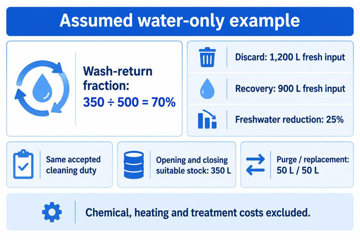
A wash-liquid recovery percentage and freshwater-saving percentage provide different types of information. A wash-liquid recovery percentage can be used to determine how much wash liquid is recovered to a tank. A freshwater-saving percentage is used to compare how much freshwater is used to perform a given service within a defined operating boundary. A fair comparison is made when the cleaning duty and acceptance endpoint are equal, liquid inventory is accounted for, and the water required to restore the recovered solution is included.
The water-use guidance offered by OSU advises users to track water inputs and outputs. Apply this concept to the proposed cleaning setup before adding plant utilities or other processes. The beginning and ending tank stock is important because drawing down stored liquid can, for a period of time, reduce freshwater purchases and create a perceived savings.
Assumed water-only example: both alternatives complete the same accepted cleaning duty. Each uses a 500 L wash charge and 700 L of rinse water. The recovery alternative starts and ends with 350 L of suitable reusable stock at equivalent chemical condition. Its additional 50 L purge and 50 L replacement include all restoration water assumed here. Chemical consumption, heating and treatment costs are outside the scope of this example.
| Water-accounting category | Discard after use | Recover selected wash |
|---|---|---|
| Opening reusable stock | 0 L | 350 L |
| Wash charge | 500 L fresh | 350 L stock + 150 L fresh |
| Fresh rinse input | 700 L | 700 L |
| Additional purge / replacement | 0 L / 0 L | 50 L / 50 L |
| Closing reusable stock | 0 L | 350 L |
| Total fresh input | 1,200 L | 900 L |
| Total discharge | 1,200 L | 900 L |
| Wash liquid retained before additional purge | 0 L | 350 L |
| Wash-return fraction | 0% | 350 / 500 = 70% |
| Freshwater reduction against discard baseline | Baseline | (1,200 − 900) / 1,200 = 25% |
For the recovery alternative, 350 L of the 500 L wash charge returns to stock before the additional purge. Its wash-return fraction is 350 ÷ 500 = 70%. Freshwater input is 150 + 700 + 50 = 900 L, compared with 1,200 L for discard after use. The freshwater reduction is (1,200 − 900) ÷ 1,200 = 25%.
The inventory also closes: 350 L opening stock + 900 L fresh input = 350 L closing stock + 900 L discharge. The recovery-side discharge includes 150 L wash, 700 L rinse and the additional 50 L purge.
Keep the denominator visible
In this example, 70% wash return produces 25% freshwater reduction. Replacing the inputs with measured plant volumes and demonstrated solution conditions turns the same ledger into a useful comparison.
Finance can then add chemical makeup, utility energy, effluent treatment and maintenance on their own measured bases. Production also needs the complete time to return equipment to service. A longer heat-up, constrained return route or delayed review can change that time even when the programmed wash interval stays the same.
Before Moving from a Guide to a CIP Project
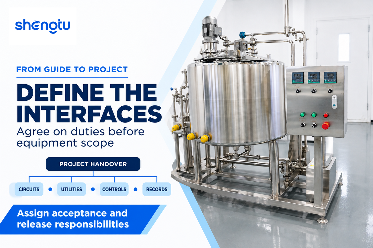
A CIP project becomes real when a plant and suppliers agree on cleaning duties and interfaces. The initial inputs to the project are the product, soil, equipment circuits, cleaning schedule, available utilities, recovery restrictions and required operating records. Those specify the system configuration and define the actual line.
In sequence, identify the most likely bottleneck as equipment readiness, supply and return availability, heating capacity during the shared schedule, phase-transition conditions, and review before release for production. Food Engineering’s Expert Interviews provide good integration examples, such as boiler capacity and connected equipment communication. The complete path being available determines the pace of the process.
For UHT and aseptic filling interfaces, assign separate cleaning and sterilization duties as part of the process design, keeping the equipment layout and evidence for the next use clear across supplier limits.
At handover, the useful package includes circuit diagrams, recipe and route lists, locations of process control instruments, interruption behavior, retained records and acceptance checks. Engineering owns the installed interface, operations needs a procedure to execute, and quality defines the checks and release responsibility. Finance can compare use of resources when the other functions integrate.
SHENGTU’s CIP cleaning system configurations provide a starting point for solutions. Share production and circuit requirements with the SHENGTU project team to agree on the scope of supply and integration.
Frequently Asked Questions
Is a sanitizing rinse the last step in every CIP cycle?
The cleaning program and sanitizing instructions determine the final actions.
Some programs include a subsequent rinse; others use a permitted no-rinse sanitizing application. The specified chemistry, water quality and equipment holding condition determine the arrangement. Drainage and protection before production are part of that finish. Follow the approved procedure and chemical label for the intended use, then complete the cleaning checks assigned to that circuit. A generic sequence diagram offers an explanation of the process rather than a plant operating instruction.
What is CIP and SIP?
CIP means clean in place; SIP generally means sterilize in place.
CIP removes soil from included process surfaces through the assigned cleaning method. Sterilization has a different microbial-control objective and requires an equipment arrangement and demonstrated process suited to that objective. Sanitizing also differs from sterilizing. In an aseptic project, define the cleaning and sterilization duties separately, including the relevant surfaces, instruments, sequence and acceptance evidence. A clear responsibility boundary helps the process-equipment supplier and cleaning-system supplier deliver their respective functions.
Which CIP cleaning system is best?
The best fit is the system that meets the defined cleaning duty under the plant’s actual conditions.
Compare product soils, circuits, cleaning frequency, utilities and recovery restrictions before selecting tank count or control functions. Include the operator tasks and records your team needs. A compact single-use arrangement can suit one duty, while a recovery arrangement can suit another. The comparison should also include the interfaces with existing process equipment, the handling of interrupted cycles and the evidence required for the next production run.
When are optional CIP steps like acid wash or air blow used?
Optional steps address a defined soil-removal or liquid-removal need.
An acid stage can address mineral deposits. Air blow or drying follows the equipment and process requirements. Their use depends on compatibility, the cleaning program and the applicable instructions.
Can an existing CIP system be upgraded without replacing the whole skid?
An upgrade can be practical when the existing equipment can support the changed duty.
Begin with the missing function: measurement, route control, recipe management, exception handling or record retention. Adding a recorder is a different project from increasing simultaneous cleaning capacity. More capacity can change pump duty, heating demand, return handling, storage and drainage. Review the installed condition, instrument locations, spare control inputs and outputs, communications and software access. The project also needs a demonstration of the changed function, backup arrangements and maintenance access. The plant’s responsible team then reviews the affected cleaning procedure and acceptance evidence before the revised arrangement enters service.
References & Sources
- Oklahoma State University Extension, What is Clean in Place (CIP)?, Timothy J. Bowser, 2023.
- University of Florida IFAS, Basic Elements of Equipment Cleaning and Sanitizing, Ronald H. Schmidt. Used for cleaning principles and terminology.
- 3-A Sanitary Standards, Cleanability of Equipment and the Role of the 3-A Sanitary Standards.
- CIP systems critical to validatable, cost-effective cleaning, Tim Bowser, 2007. System-configuration definitions.
- Food Engineering, Make CIP an Integral Part of Your Process, Wayne Labs, 2023. Original industry interviews.
- Food Engineering, Tech Update: Clean-in-Place, Wayne Labs, 2008. Historical soup-plant implementation.
- Food Engineering, Tech Update: Clean-in-Place Equipment, Wayne Labs, 2010. Component and return-system context.
- Oklahoma State University Extension, Reducing Water Use in Food Processing, Tim Bowser, 2016.
- Fan, Kim and Heldman, Influence of cleaning agent reuse on cleaning effectiveness, Journal of Food Engineering, 2022. University-hosted original abstract.
- Process Online, CIP process efficiency: real-time monitoring and control, Part 2, Endress+Hauser Australia, 2017. Vendor-authored instrumentation feature.
- FDA, Appendix 10: Cleaning and Sanitation for the Control of Allergens, 2019. Seafood-processing guidance; used within its stated scope.
![Meat / Poultry / Prepared: Plant Planning Guide [2026]](https://shengtumachinery.com/wp-content/uploads/2026/10/meat-poultry-prepared-processing-guide-featured-768x512.png)
![Beef/Lamb/Poultry Cutting Line Acceptance Guide [2026]](https://shengtumachinery.com/wp-content/uploads/2026/09/beef-lamb-poultry-cutting-line-guide-featured-150x150.png)
![Dry Kibble Extrusion Line: Process Control Guide [2026]](https://shengtumachinery.com/wp-content/uploads/2026/08/dry-kibble-extrusion-line-guide-featured-150x150.png)
![F&V Freeze-Drying Line Process Guide [2026]](https://shengtumachinery.com/wp-content/uploads/2026/09/fv-freeze-drying-line-guide-featured-150x150.png)


