Get in touch with Shengtu Bufan Company

Updated September 2026
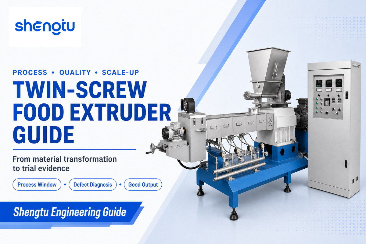
A twin-screw food extruder is a continuous processing system in which two screws convey, mix, heat, shear, pressurize, and shape a formulated food mass. The machine matters, but the result comes from the interaction among the recipe, moisture distribution, screw elements, feed rate, temperature, die resistance, and the drying or cooling steps that follow.
This guide helps food technologists, project engineers, and plant teams turn those interactions into a process brief and a defensible trial plan. It intentionally does not repeat model, configuration, price, or quotation content. Those commercial decisions belong on Shengtu’s dedicated equipment page after the process requirement is clear.
The short answer
A twin-screw food extruder turns a controlled ingredient feed into a repeatable material state, then forces that material through a die to create the intended shape and structure. Its purpose is not merely to push product through a barrel; it is to maintain a measurable process window that produces acceptable texture, density, dimensions, moisture, and line stability.
Guide map
- What the extruder actually does
- How material moves through the process
- Single-screw versus twin-screw fit
- Application-to-Process Evidence Grid
- Building a measurable process window
- Texture Failure Ladder
- Good-kilogram capacity
- Trial-to-Scale Acceptance Protocol
- Sanitation, wear, and safe intervention
What Does a Twin-Screw Food Extruder Actually Do?

Twin-screw food extrusion continuously meters, conveys, mixes, heats, shears, pressurizes, and shapes food material. Its two screws can arrange conveying and mixing elements in a sequence suited to a defined transformation, but the finished product still depends on the complete recipe and line.
The screws do several jobs at once. Conveying elements move material forward. Mixing elements redistribute water, fat, minor ingredients, and heat. Mechanical work and barrel heating change viscosity and promote cooking or texturization. Restriction near the die builds pressure, and the die converts the conditioned mass into a chosen geometry. At the outlet, pressure release can contribute to expansion, while the cutter, dryer, cooler, or cooling die determines what happens next.
Co-rotating intermeshing designs are common where recipe flexibility and mixing control matter. That does not make twin-screw technology universally superior. Stable, free-flowing recipes with a narrow operating range may be handled efficiently by a simpler system. The better question is whether the product needs positive conveying, configurable mixing, liquid addition, venting, or control across changing raw materials.
Unlike plastic extrusion, food extrusion may combine a variable powder blend with water, steam, fat, and heat-sensitive ingredients. Modular screw layouts can place conveying and mixing functions where the tested recipe needs them, but those elements still must be validated as one process rather than selected from a generic diagram.
The extruder also is not the whole production line. Short feeder disturbances can look like an extrusion problem. Available motor load does not prevent a dryer from capping output. Stops at a cooler or packer reduce scheduled production. For this reason, define the system from ingredient receiving through acceptable packed product, not from hopper to die only.
Terminology boundaries for food production
The working principle is continuous: a rotating screw pair works inside a barrel, and an intermeshing screw design may be either co-rotating or counter-rotating. The types of twin screw extruders also include parallel or conical arrangements, but those labels alone do not predict consistent product quality. Sound extruder selection still starts with the recipe and product test.
Modern food manufacturers may use the extruder to compound complex formulations, run a small batch during development, or support steady food production. Compared to batch processing, the line records a continuous material history along the barrel. Screw design, process control, precise temperature control, residence time and temperature, and the temperature zones along the barrel must still be interpreted with feed behavior and the finished result. Claims of superior mixing or excellent mixing are not acceptance evidence by themselves.
Common applications across food industries include dry pet food, breakfast cereals, protein products, snacks, and other diverse applications. An extruder is used for many product categories, but that list does not prove one configuration can make them all. Search results may also discuss active pharmaceutical ingredients; that subject sits outside this food guide and should not influence a food-process decision.
How Does Material Move Through the Food Extrusion Process?
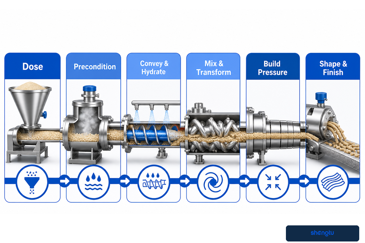
Material normally moves from dosing and optional preconditioning through solids conveying, hydration, cooking or texturization, pressure build, die shaping, cutting, and downstream drying or cooling. Although the barrel has physical zones, the material state changes continuously, so operators should follow moisture, temperature, mechanical energy, and pressure together.
In a twin screw extrusion process, the useful question is not where one named zone ends. It is whether the recorded material state remains connected to the food extrusion process result that the product test accepts.
Food extrusion process flow
1. Dose→
2. Precondition→
3. Convey & hydrate→
4. Mix & transform→
5. Build pressure→
6. Shape & finish
2. Precondition→
3. Convey & hydrate→
4. Mix & transform→
5. Build pressure→
6. Shape & finish
Dosing creates the recipe on a time basis. If ingredients segregate or a feeder pulses, the average formula may look correct while the extruder receives alternating rich and lean pockets. Preconditioning can add water or steam and start thermal processing before the barrel. This may reduce the transformation duty inside the extruder, but only when residence time, mixing, and inlet condition are controlled.
Inside the barrel, conveying and mixing redistribute the feed while heat enters from both the barrel and mechanical work. Pressure usually rises toward the die, but torque, product temperature, and pressure are responses, not independent quality buttons. The peer-reviewed review of food extrusion variables describes screw speed, feed rate, moisture, temperature, torque, die pressure, screw configuration, particle size, and ingredient proportion as interacting factors.
At the die, the material experiences a rapid geometry and pressure change. Expanded products rely partly on controlled flashing and structure setting. Dense pellets may need limited expansion. High-moisture protein products use a different route: a cooling die removes heat and helps structure develop while limiting flash expansion. One unqualified “best recipe” cannot cover those different mechanisms.
Single-Screw vs Twin-Screw: Which Process Conditions Favor Each?

Single-screw extruders can suit a consistent, free-flowing recipe with a comparatively narrow processing duty. Twin-screw extruders become attractive when the feed is harder to convey, the formulation varies, stronger mixing is needed, or the process must combine several functions with tighter control.
Screw count is not a food-quality ranking. The DLG’s technical report on extrusion distinguishes simpler applications that may suit single-screw processing from formulation and feeding conditions where twin-screw modularity adds value. The 2025 aquafeed review likewise frames versatility alongside higher capital, energy, and maintenance demands in its specific context. Those comparisons are decision boundaries, not universal cost multipliers.
| Question | Conditions that may favor single screw | Conditions that may favor twin screw |
|---|---|---|
| Feed behavior | Stable, free-flowing, low variation | Variable, sticky, multi-component, or difficult to feed |
| Mixing duty | Limited redistribution or simple cooking/forming | Distributive or dispersive mixing, liquid addition, staged functions |
| Operating envelope | Narrow recipe and moisture range | Wider formulation range or frequent development work |
| Decision proof | Stable feed and accepted product at required good output | Same proof, plus evidence that added flexibility is actually used |
Once the recipe duty and acceptance method are defined, review available twin-screw food extruder configurations on the solution page. Keeping model selection there prevents this guide from competing with the commercial page for quotation intent.
Use the 5-Column Application-to-Process Evidence Grid
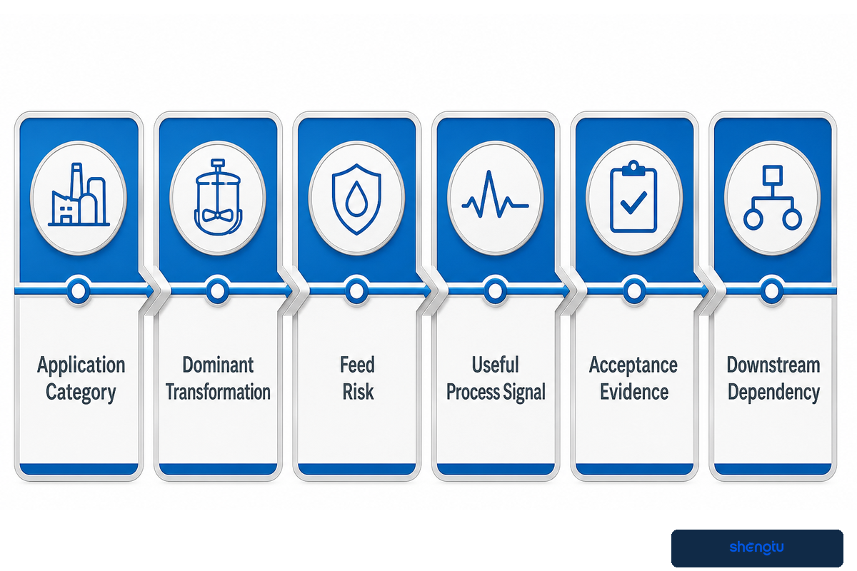
The Application-to-Process Evidence Grid links each food category to the transformation, feed risk, in-process signal, product test, and downstream dependency that a trial must prove. It prevents a list of possible products from being mistaken for evidence that one configuration can make them all.
| Application category | Dominant transformation | Feed risk | Useful process signal | Acceptance evidence | Downstream dependency |
|---|---|---|---|---|---|
| Expanded snacks / cereals | Cooking, expansion, shape | Moisture and particle variation | Torque, product temperature, die pressure | Bulk density, expansion, texture, color | Drying and coating |
| Pet food | Cooking, forming, density control | Fat, fiber, protein, palatant plan | Load, pressure, stability | Dimensions, density, durability, final moisture | Dryer, cooler, coater |
| Low-moisture TVP | Protein texturization and expansion | Protein functionality and hydration | Energy, temperature, pressure | Structure, rehydration, density | Drying and size reduction |
| High-moisture protein | Protein alignment and cooling-set structure | Protein source, hydration, heat sensitivity | Load, product temperature, die thermal behavior | Fibrous structure, integrity, cooking performance | Cooling die and cutting |
| Pellets / semi-finished pieces | Cooking, densification, controlled shape | Binder and moisture distribution | Pressure, torque, cutter stability | Geometry, breakage, later expansion behavior | Drying and secondary processing |
| Aquatic feed | Cooking, density, water stability | Oil, fiber, fines, ingredient variation | Load, pressure, product temperature | Float/sink behavior, durability, water stability | Drying, oil application, cooling |
| Instant cereal / flour | Cooking, agglomeration, solubility change | Starch type and powder flow | Energy, temperature, rate stability | Dispersibility, viscosity, moisture | Drying, milling, screening |
| Filled / co-extruded snacks | Shell formation and filling coordination | Shell and filling rheology | Pressure, shell rate, filling rate | Wall thickness, seal, fill ratio | Co-extrusion head, cutting, drying |
| Bread crumbs / porous intermediates | Cooking, controlled expansion, later milling | Color and moisture uniformity | Temperature, density, line rate | Porosity, color, particle distribution after milling | Drying, cooling, milling, screening |
Use the grid to decide what data must travel with every sample. For example, an expanded snack sample without its conditioning time and moisture result is hard to compare. Without cooling-die conditions, a high-moisture protein sample says little about scale-up. The grid does not pick a screw configuration; it makes the missing evidence visible before configuration begins.
Build a Process Window Around Measurable Product Quality
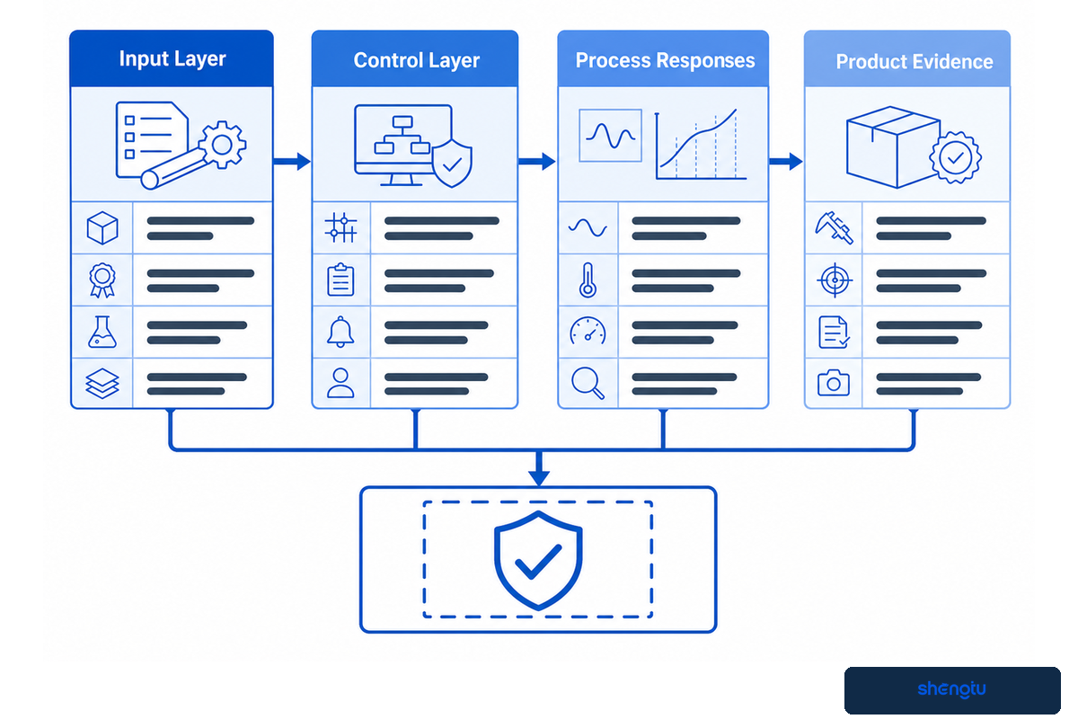
A process window is a bounded combination of material inputs and machine responses that repeatedly produces an accepted product. It should connect formulation and operating conditions to measured signals and product tests, rather than preserve one temperature or screw-speed number in isolation.
Decision principle: A stable machine is not the same as accepted food extrusion quality. Release evidence must connect the recorded process state with the agreed product test.
Begin with the input layer: formula, supplier and lot, particle-size distribution, initial moisture, preconditioning, solid feed rate, and added water or steam. Record the control layer next: screw speed, screw-element sequence, barrel-zone settings, die geometry, cutter condition, and any venting or side feeding. Then capture responses such as torque or motor load, specific mechanical energy where available, product temperature, melt pressure, residence behavior, and throughput stability. Use explicit units in the record—for example mm for dimensions, kg/m³ for bulk density, N for breaking force, % for moisture, °C for temperature, bar for pressure, kW for power, kg/h for rate, and min for sampling intervals—without treating any example unit as a universal target.
The final layer is product evidence. Depending on the application, that may include expansion ratio, bulk density, breaking force, texture profile, final moisture, dimensions, color, piece uniformity, cooking behavior, or rehydration. The 1994 system-analysis experiment varied moisture and screw speed while tracking torque, specific mechanical energy, product temperature, and die pressure. Its lasting lesson is the structure of the evidence chain: input, process response, and product result must be interpreted together.
| Recorded field | Example notation only | Why it stays in the evidence chain |
|---|---|---|
| Particle size | 0.1 mm | Feeding and hydration context |
| Solid feed rate | 1 kg/h | Normalizes material input |
| Water-addition rate | 0.1 kg/h | Tracks the moisture route |
| Steam-addition rate | 0.1 kg/h | Tracks thermal preparation |
| Initial moisture | 0.1% | Separates raw-material and process water |
| Screw speed | 1 rpm | Defines a major control input |
| Barrel setting | 1°C | Records the commanded thermal profile |
| Product temperature | 1°C | Records a material response |
| Die pressure | 0.1 bar | Shows resistance and stability |
| Motor power | 0.1 kW | Supports energy calculation |
| Sampling interval | 1 min | Links trends to samples |
| Stable-window duration | 1 min | Defines the reviewed period |
| Piece length | 0.1 mm | Quantifies cutter and die results |
| Piece diameter | 0.1 mm | Quantifies shape variation |
| Bulk density | 1 kg/m³ | Connects structure with packing behavior |
| Breaking force | 0.1 N | Quantifies texture under one method |
| Final moisture | 0.1% | Checks downstream completion |
| Dryer residence time | 1 min | Defines downstream exposure |
| Cooling temperature | 1°C | Confirms packing condition |
| Breakage mass | 0.1 kg | Supports yield accounting |
| Runtime | 0.1 hr | Supports scheduled-output calculation |
| Wear clearance | 0.01 mm | Links inspection with drift |
| Electrical frequency | 1 Hz | Documents the utility basis |
| Compressed-air pressure | 0.1 bar | Documents an auxiliary condition |
| Control-signal voltage | 1 V | Documents an interface signal |
Practical rule
Do not copy a published setting as a guaranteed recipe. Use published research to choose variables and measurements, then establish the operating range with the actual formulation, equipment geometry, and acceptance method.
When a product changes, re-check the boundary. Changing the protein source, fat level, starch system, particle size, or flavor carrier can alter feeding, viscosity, energy transfer, and die behavior. Mechanical stability can coexist with unacceptable food, so “the extruder ran” is not a sufficient release decision.
Diagnose Defects with the Texture Failure Ladder
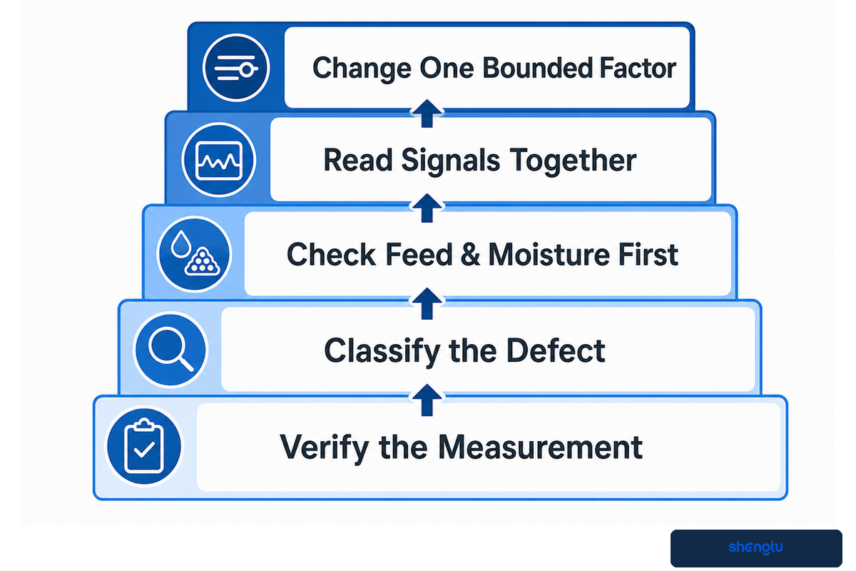
The Texture Failure Ladder moves from measurement verification to defect classification, feed and moisture checks, combined process-signal review, and one bounded change. It reduces the common mistake of adding heat or screw speed before confirming that the defect and its upstream cause are real.
- Verify the measurement. Condition samples the same way, use the same test method, and confirm the instrument or visual standard.
- Classify the defect. Separate density or expansion, hardness or internal structure, surface or color, size uniformity, and line stability.
- Check feed and moisture first. Review feeder variation, water addition, preconditioner discharge, ingredient segregation, and lot changes.
- Read signals together. Torque, pressure, product temperature, and rate can distinguish a process shift from a downstream or sampling issue.
- Change one bounded factor. State the hypothesis, hold other variables as steady as practical, record the response, and return to baseline if quality worsens.
| Defect | Check first | Read together | Avoid |
|---|---|---|---|
| Low or drifting expansion | Sample moisture, feed consistency, die condition | Density, product temperature, pressure, load | Increasing temperature automatically |
| Excessive hardness | Conditioning method, moisture route, structure | Energy, density, final moisture, drying history | Blaming the die alone |
| Surging or nonuniform pieces | Feeder, bridging, water pulse, cutter | Rate, torque, pressure, piece distribution | Using only average throughput |
| Dark specks or scorching | Hold-up, dead zones, shutdown history, ingredient sensitivity | Temperature, residence behavior, visual trend | Assuming color is only a recipe issue |
| Wet product after dryer | Inlet moisture, bed loading, airflow, residence distribution | Extruder output, dryer load, final-moisture distribution | Reducing extrusion rate without finding the dryer limit |
Calculate Capacity as Good Kilograms, Not Nameplate Kilograms
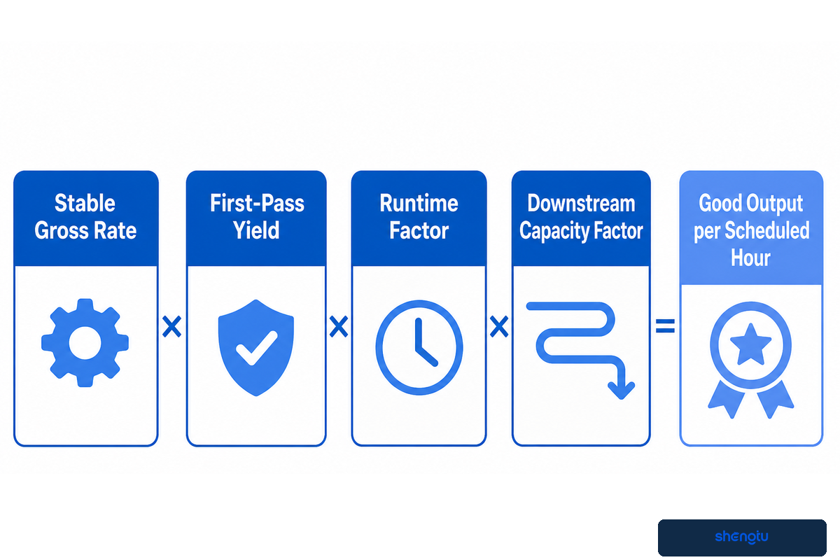
Useful capacity is the accepted product delivered by the complete line during scheduled time. Estimate it by discounting stable gross extrusion rate for first-pass yield, runtime, and the capacity factor of the limiting downstream station.
Good-Kilogram Capacity Discount Worksheet
Good output per scheduled hour = stable gross rate × first-pass yield × runtime factor × downstream capacity factor
Every factor must come from the actual plant boundary or a representative line trial. Do not treat the worksheet as a machine guarantee.
Hypothetical planning example: suppose a line demonstrates a stable gross rate of 500 kg/h for the test product. If measured first-pass yield is 94%, the planned runtime factor is 85%, and the downstream system can sustain 90% of that stable gross rate, the planning estimate is 500 × 0.94 × 0.85 × 0.90 = 359.6 good kg per scheduled hour. These numbers are illustrative only; they are not Shengtu specifications or promised performance.
The downstream factor prevents nameplate arithmetic from hiding the real constraint. Dryer residence time may be the first hard limit when final-moisture distribution matters. Cooling must stabilize the product before packing, while a coater may have a narrower application range than the extruder. Cutters, conveyors, and packing machines can also limit acceptable throughput or increase breakage.
Ask for both the constraint and the evidence. If the dryer is limiting, record bed loading, time, airflow conditions, and final-moisture distribution. If the feeder is limiting, retain rate variability rather than only the average. If product quality fails first, the process window—not motor power—sets the capacity. The lowest repeatable accepted constraint is the defensible line rate.
Validate a Trial with the Trial-to-Scale Acceptance Protocol
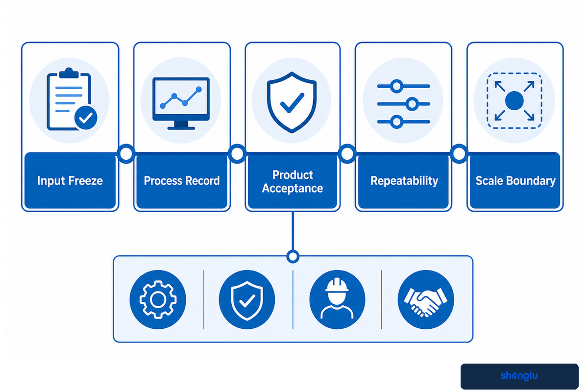
The Trial-to-Scale Acceptance Protocol freezes representative inputs, records the process state, tests the product, proves repeatability, and documents what may change at larger scale. It replaces a successful sample photo with an evidence package that engineering, quality, operations, and the supplier can review together.
Trial-to-Scale Acceptance Protocol
- Input freeze: recipe revision, supplier and lot, particle size, starting moisture, preconditioner settings, and measurement methods.
- Process record: feed rate, water or steam addition, screw speed, barrel settings, load or torque, pressure where available, and product temperature.
- Product acceptance: moisture, bulk density, texture, dimensions, color, breakage, and application-specific tests.
- Repeatability: repeated sampling across a declared stable window, plus startup, restart, and changeover observations where relevant.
- Scale boundary: changes expected with screw diameter, die area, feed behavior, thermal history, dryer loading, and auxiliary equipment.
High moisture extrusion shows why this discipline matters. The 2025 peer-reviewed review identifies protein source, input composition, extruder configuration, and process parameters as joint development variables. Another 2025 study describes complex transformations in the heated twin-screw barrel and cooling die while comparing machine-learning and conventional optimization. More data can improve a model, but it does not remove the need for representative material and physical acceptance tests.
Lab or pilot runs can identify direction and reject weak formulations, yet scale changes surface-to-volume relationships, screw geometry, heat transfer, die area, residence distribution, and auxiliary-equipment loading. Therefore, separate “the sample met its test on this setup” from “the result will transfer unchanged.” Record assumptions that require confirmation during factory acceptance and commissioning.
The protocol should also state who owns each decision. Food technologists approve formula and product methods. Quality teams approve sampling and release rules. Engineering confirms utilities, controls, and interfaces. Operations checks cleaning, staffing, and restart behavior. The supplier documents machine conditions and open technical actions. The trial is complete when these parties can trace a product result to a defined input and process state.
Plan Sanitation, Wear Control, and Safe Intervention

A dependable extrusion plan maps food-contact access, allergen and changeover risks, wear points, and safe servicing before production starts. Routine sanitation and stored-energy control are related operational concerns, but they require distinct plant procedures and verification.
Start with product contact and residue movement. Identify zones that are visible and directly cleanable, parts that require removal, seals or joints that can retain material, and the route for purged product. Define the inspection or test that ends a changeover. For allergen work, include production sequence, rework handling, shared utensils, and the evidence required before release.
The FDA’s preventive-controls guidance connects sanitation controls with food-safety risks, allergen cross-contact, and contamination. It does not supply a universal cleaning frequency for every extrusion recipe. The processor must build and validate a food-safety plan for the actual product, equipment, sequence, and jurisdiction.
Wear changes more than maintenance cost. Screw and barrel clearance can alter conveying, energy transfer, pressure behavior, and residence history. Worn die openings or cutter parts change geometry and piece distribution. Track dimensional inspections together with process trends and product results. Slow increases in load or a drifting density distribution can become investigation triggers, but they are not proof of one particular wear mechanism.
Opening, unjamming, or servicing an extruder presents a different boundary. OSHA’s 29 CFR 1910.147 covers servicing and maintenance in the United States where unexpected energization, startup, or stored energy could cause injury. The plant’s documented energy-control procedure, risk assessment, local requirements, and manufacturer instructions govern the intervention. This guide is not a substitute for those documents.
Decision Framework Before You Send a Process Brief
A useful process brief defines the target product, recipe envelope, good-output requirement, complete-line scope, utilities, cleaning boundary, and trial acceptance method. Only then should it hand the project to a supplier for machine configuration.
| Decision block | What to define | Acceptance evidence |
|---|---|---|
| Product target | Dimensions, density, texture, final moisture, allowed variation | Methods, conditioned samples, tolerance table |
| Recipe envelope | Major materials, lot variation, moisture, sensitivity, allergens | Representative trial materials and revision control |
| Production need | Good output, schedule, changes, planned stops | Sustained line record and yield accounting |
| Complete-line scope | Dosing, preconditioning, extrusion, finishing, packing | Interface list and limiting-station test |
| Trial proof | Signals, sampling, methods, stable period, scale boundary | Signed protocol, data export, samples, open-action list |
Shengtu Machinery describes its food-processing equipment and turnkey-line work on the company background page. Use that context to understand the organization; use the documented product target and trial evidence to judge project fit.
When the brief is ready, take it to the Twin-Screw Food Extruder solution page for configuration discussion. This sequence keeps the informational and commercial search intents distinct: the guide explains how to decide and validate, while the solution page handles what Shengtu can configure and supply.
Bring a process brief, not just a product name
Share the recipe envelope, target quality, good-output requirement, downstream scope, and trial acceptance method. That gives the engineering discussion a testable starting point.
Frequently Asked Questions
What is the purpose of a twin screw extruder?
A twin-screw food extruder creates a controlled material transformation by continuously conveying, mixing, heating, pressurizing, and shaping food while holding a repeatable process window across the complete line.
Twin-screw extrusion continuously converts a metered food formulation into a shaped product by combining conveying, mixing, heating, mechanical shear, and pressure generation. Its practical value is controllability: teams can configure screw functions and adjust feed, moisture, temperature, and die resistance to create a defined material state. The purpose is not simply to push ingredients through a barrel; it is to hold a repeatable process window that produces acceptable texture, density, shape, and moisture. That window must include the feeder and downstream steps because a stable barrel cannot correct an intermittent recipe feed or an undersized dryer. The real purpose is therefore a controlled, traceable transformation across the complete line. Saved trends, timed samples, and defined product tests show whether that transformation is repeatable enough for the next scale.
What is the difference between a single screw extruder and a twin screw extruder?
Single-screw and twin-screw extruders differ mainly in conveying, mixing, and process flexibility. The appropriate system depends on feed behavior and transformation duty, not a simple food-quality ranking.
Single-screw extrusion generally depends more on friction and steady feeding, and it can be efficient for consistent recipes with a relatively narrow operating window. Twin-screw systems provide stronger mixing, a more flexible screw-element arrangement, and better handling of some variable or high-moisture formulations. The right choice still depends on the product, feed behavior, control requirement, cleaning needs, and economics; screw count alone does not determine final food quality.
What are the downsides of food extrusion?
Food extrusion couples many variables, so startup loss, wear, cleaning demands, operator skill, and downstream bottlenecks can reduce useful output even when the extruder itself appears stable.
Food extrusion couples many variables, so a change in moisture, feed rate, screw speed, die restriction, or downstream drying can alter several quality attributes at once. Startup loss, wear, cleaning, operator skill, and line bottlenecks also affect usable capacity. Excess heat or shear can damage color, flavor, texture, or sensitive components, while insufficient processing may miss the intended structure. That is why a controlled trial and defined acceptance plan are more reliable than copying another product’s settings.
Can twin-screw extruders handle high-moisture formulations?
Twin-screw extruders can often handle high-moisture formulations, but capability must be demonstrated with the actual protein system, moisture range, production target, cooling route, and product acceptance tests.
High-moisture processing changes feeding, thermal control, die or cooling requirements, and the way structure develops. Suitability must be tested with the actual protein system, moisture range, throughput target, and downstream cooling or cutting method. Treat “high moisture capable” as a process-development question, not a complete specification, and record what may change between pilot and production scale.
How do you estimate useful production capacity?
Estimate useful capacity by discounting the measured stable gross rate for first-pass yield, scheduled runtime, and the limiting downstream factor, then report accepted product per scheduled hour.
Start with the measured stable extrusion rate for an accepted product, then discount it by first-pass yield, scheduled runtime, and the capacity factor of the slowest downstream step. This gives good kilograms per scheduled hour, which is more useful than a single nameplate figure. Use representative trial records and product acceptance data for every factor, and identify the station that becomes limiting first.
Which process data should a factory collect during a trial?
A factory trial should record material identity, feed and liquid rates, screw speed, temperatures, load, pressure, sample time, downstream conditions, and final product quality as one traceable evidence set.
At minimum, record recipe and lot, feed rate, water or steam addition, screw speed, temperature profile, motor load or torque, die pressure where available, product temperature, sample time, and downstream conditions. Pair those records with agreed product measurements so the team can connect process changes to actual quality. Include startup, restart, and changeover observations when they matter to scheduled output.
Editorial and evidence method
This article separates educational process, troubleshooting, and trial guidance from Shengtu’s commercial product page. It uses current public regulatory, peer-reviewed, independent technical, patent-mechanism, and first-party site evidence. Research settings and the hypothetical capacity calculation are not presented as universal operating values or machine guarantees.
References & Sources
- High-moisture extrusion of plant proteins: fundamentals and opportunities — peer-reviewed review indexed by PubMed.
- Extrusion Process as an Alternative to Improve Pulses Products Consumption — peer-reviewed open-access review.
- Machine-learning optimization of high-moisture protein extrusion — peer-reviewed open-access study.
- System analysis of a twin-screw food extrusion process — Food Control.
- DLG Expert Report 02/2022: Extrusion — independent food-industry technical report.
- Single- and twin-screw extrusion in aquafeed processing — peer-reviewed 2025 review.
- Hazard Analysis and Risk-Based Preventive Controls for Human Food — U.S. Food and Drug Administration guidance.
- 29 CFR 1910.147: Control of Hazardous Energy — U.S. Occupational Safety and Health Administration.
- US7275927B2 cooling-die record — mechanism context only, not freedom-to-operate advice.